Modernizing a Winchester 37
by Roy Seifert
Click here to purchase a
CD with this and all Kitchen Table Gunsmith Articles.
Disclaimer:
This article is for entertainment only and is not to
be used in lieu of a qualified gunsmith.
Please defer all firearms work to a qualified
gunsmith. Any loads
mentioned in this article are my loads for my guns and have
been carefully worked up using established guidelines and
special tools. The
author assumes no responsibility or liability for use of
these loads, or use or misuse of this article.
Please note that I am not a professional gunsmith,
just a shooting enthusiast and hobbyist, as well as a
tinkerer. This
article explains work that I performed to my guns without
the assistance of a qualified gunsmith.
Some procedures described in this article require
special tools and cannot/should not be performed without
them.
Warning:
Disassembling and tinkering with your firearm may
void the warranty. I
claim no responsibility for use or misuse of this article.
Again, this article is for entertainment purposes
only!
Tools
and firearms are the trademark/service mark or registered trademark
of their respective manufacturers.
Introduction
About 20+ years ago a coworker approached me and wanted to
know if I was interested in purchasing an old single-shot
shotgun. I asked him if he had any details about the gun
and he told me that it was owned by his father which he had
inherited when his father passed away. I told him I would
be interested so he brought it into work (this was when we
could still do those things!) and we went out to the parking
lot so I could take a look.
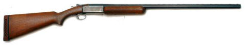
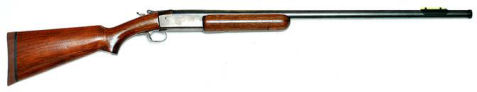
It turned
out to be a single-shot, break-open 12 gauge Winchester
model 37 Steelbilt with a 30” full-choke barrel and an
external hammer. The Winchester 37 was manufactured from
1936 until 1963 and most did not have a serial number.
Because it was manufactured before 1968 it is legal to own
without a serial number. This gun is a classic piece of
Winchester workmanship. Who knows how much game this gun
has harvested over the years? It had a lot of surface rust
on the barrel from being stored under my coworker’s bed for
years, but some 000 steel wool and gun oil took care of
that. The receiver was starting to take on a plum color,
but other than those two issues, the gun was in excellent
condition. The bore was clean and bright with no pitting.
I used
this gun for trap shooting at one time, but I hadn’t used it
for years. Since I have been working on shotguns lately,
(refer to my article
Modifying a Winchester 97 for Competition) I decided
I wanted to modernize this old gun. My modernizing plan was
as follows:
-
Measure the chamber to make sure it would take modern 2
3/4“ shells. If not, then
-
Lengthen the chamber to take modern 2 3/4“ shells
-
Lengthen the forcing cone
-
Ream
and tap the barrel for interchangeable choke tubes
-
Replace the hammer
-
Replace the poorly-fitted recoil pad
-
Install a fiber-optic bead
-
Refinish the wood
Measure
the Chamber
Even
though the chamber was stamped for 2 3/4” shells, the
chamber gauge
#080-546-012 I purchased from Brownells would not fit up
to the 2 3/4“ mark. This meant the chamber was probably
designed for 2 3/4“ roll-crimp paper shells, not star-crimp
plastic shells. The forcing cone was also very abrupt so I
wanted to lengthen both the chamber and forcing cone.
Lengthen
the Chamber and Forcing Cone
A long,
gradual forcing cone can enhance the accuracy of a shotgun
because it doesn’t deform the shot so much. Since I also
wanted to lengthen the chamber to shoot 2 3/4“ plastic
star-crimped shells; I could perform both processes at the
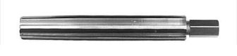
same time with a long forcing cone reamer Brownells
#080-661-012.
I removed
the barrel from the receiver, then removed the extractor,
extractor guide, extractor sear and extractor spring from
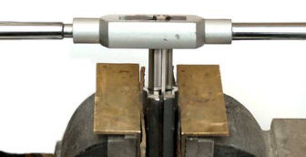
the barrel. I installed the barrel in a padded vise with
the chamber up. I lubricated the long forcing cone reamer
with cutting oil and used a large tap handle to ream the
chamber and extend the forcing cone. Because the reamer had
straight flutes, when the flutes became full with chips, the
reamer became difficult to turn. I removed it from the
barrel always turning it clockwise to prevent breaking the
teeth, and cleaned off the chips. Each time I removed the
reamer I also cleaned the chips out of the barrel with brake
parts cleaner and checked the chamber with the chamber
gauge.
I stopped
reaming the chamber and forcing cone when the chamber gauge
fit up to the 2 3/4“ mark. I could have continued
lengthening the chamber to accommodate 3” shells, but this
gun was never designed for them so I stopped at the 2 3/4“
length.
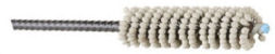
To finish
the job I polished the chamber and new forcing cone with a
12-gauge chamber Flex-Hone® I purchased from Brownells
#080-608-512. This tool is a wire brush with abrasive
balls on the ends of the bristles and comes with a nine-inch
shaft. It should only be used with Brownells Flex-Hone® Oil
#080-008-609 to ensure the polishing is performed
correctly. I attached the hone to my drill and applied the
oil to the hone. I polished the chamber and forcing cone by
running the drill at a slow speed (<750 RPM) and moving it
in and out. I flushed the barrel with brake parts cleaner,
then oiled it with CLP. Now the chamber and forcing cone
are clean and polished smooth.
Ream and
Tap the Barrel for Interchangeable Choke Tubes
In order to ream the barrel for interchangeable choke tubes
the barrel had to be at least 0.845” thick. The barrel
measured 0.850” thick 1 1/2“ back from the muzzle. Cutting
the barrel at this point also removed the fixed choke, but
wouldn’t make all that much difference to the performance of
the gun. Before cutting the barrel I marked it 3 1/2-inches
behind the original bead with a center punch so I would know
where to drill and tap the barrel to move the bead. This
location would be behind the choke tube where the barrel was
nice and thick.
I have
done this process before on other shotguns; refer to my
articles
Threading a Shotgun Barrel for Choke Tubes and
Modifying a Winchester 97 for Competition for
details. After cutting the barrel I set it vertically in my
bench vise with the muzzle up and began reaming the barrel.
To facilitate the reaming process I put about 50-pounds of
bullets on top of the tap handle. I reamed the barrel until
the shoulder of the reamer squared off the front of the
muzzle. I used a rubber polishing wheel to round off the
sharp edge on the outside of the muzzle left from cutting
the barrel, then cold-blued the exposed metal. I then
tapped the barrel using the choke tube tap. I cleaned and
lubricated the new threads and installed a Winchoke® full
choke tube. Before installing the choke tube I lubricated
the threads with choke tube lube. This prevents the choke
tube from becoming stuck as the barrel heats up from firing.
I
purchased a 3-56 shotgun sight convenience kit from
Brownells
#078-021-256 that included a #45 drill bit, and a 3-56
bottoming tap. I used the #45 drill bit to drill a hole in
the barrel where I had marked it previously. To start the
tap perfectly straight in the new hole, I left the chuck of
my drill press centered over the hole, put the 3-56 tap into
the hole, then tightened the chuck just enough so the tap
would turn freely. I used a set of vise-grips to start the
tap about 2 turns; I reversed the direction of the tap after
every 1/4 turn to break the chips. After the tap was
started I used a small tap handle to finish tapping the
hole. I cleaned the hole and the threads of the original
silver bead with acetone, then applied a small bit of blue
thread locker and installed the bead.
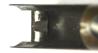
Replace
the Hammer
This shotgun had a very small, curved spur on the hammer
(Winchester calls it a cocking lever) and the knurling was
worn almost smooth. It took so much thumb pressure to cock
the shotgun my thumb would be very tired and sore after
shooting a couple rounds of trap.
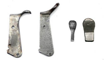
I found a
replacement hammer on
ebay, of all places, for $15.00 with free shipping.
That was cheaper than from
Numrich. If you notice in the above photo my hammer has
a thin curved spur, whereas the new hammer has a wide
straight spur. Although I can’t find any manufacturing
records for this gun, I’m guessing my gun was an early
production model. Customers probably complained about how
difficult it was to cock the gun so Winchester redesigned
the hammer with a straight spur. As a side note; a friend
of mine also has a Winchester 37 and his hammer has a wider
spur, but it is still curved, not straight. It seems that
this hammer went through a number of production changes.
After I
removed the butt stock from the receiver I could see that
two pins held the hammer in place. The top pin connected
the firing pin to the hammer, and the bottom pin was the
hammer pivot pin. I removed the two pins and withdrew the
hammer from the receiver.
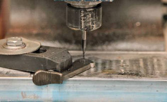
The pivot
hole in the new hammer was too small for the original pivot
pin so I tried to ream it with a drill bit, but because the
hammer was hardened I broke the bit. I had to set up my
hobby CNC milling machine to mill the proper diameter hole
of 0.080”. I used a 1/16” square end bit and milled 0.0005”
deep each pass and kept it well oiled.
I
installed the hew hammer into the receiver and found that
the trigger sear did not fit into the ‘V’ notch in the front
of the hammer. I used my high speed rotary tool and a
cutoff wheel to expand the ‘V’ notch, then polished it with
a fine stone. The straight spur now makes the gun very easy
to cock and the trigger sear fits into the ‘V’ notch.
Replace
the Poorly Fitted Recoil Pad
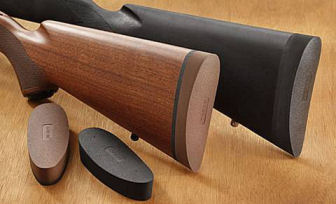
(Photo courtesy of Hogue)
I
purchased a brown Hogue EZG grind to fit recoil pad size
medium
#00711 from the
eCop Police Supply web store on eBay. I purchased brown
because I thought it would nicely set off the refinished
stock.
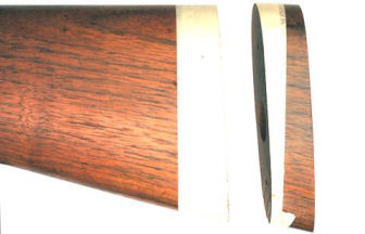
Since the
pad measured one-inch thick I cut one-inch off of the butt
stock. I put two layers of masking tape around the stock
and cut it to the same angle of pitch. I don’t remember
where I read this, but somewhere I read that you need to use
a sharp saw blade to prevent splintering the wood. I
purchased a new blade for my table saw that cost $60, and it
not only cut the walnut like it was butter, but left no
splintering.
After
cutting the butt stock, I marked and drilled new holes for
the recoil pad. I mounted the pad onto the stock and
scribed a line around the stock. I have trouble seeing the
scribed line, so I filled it with white paint. I painted
the scribe line, then wiped off the excess paint with an
alcohol-soaked cloth. This made the scribe line stand out
so I could see it better. This worked so well that even my
errors and overruns showed up.
I then
sanded the pad using my modified jig and sanding table. For
details refer to my article
Installing a Recoil Pad. Every time I do this I get
better at it, and the white line really helped me from
sanding too far.
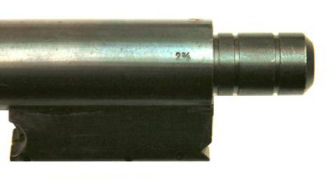
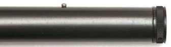
Installing a Fiber Optic Bead
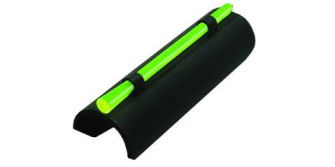
My
Winchester 1300 Defender came with a slip-on fiber-optic
front sight. In reality it was a
Hiviz MPB sight. It slips on over the barrel, and a
V-notch in front sits against the bead which prevents the
sight from moving under recoil.
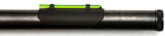
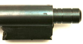
Since I
use an electronic holographic sight for my Defender, I took
the slip-on bead off of the Defender and put in onto the 37
barrel. As you can see from the above photo it sets back a
ways from the muzzle, but that green dot is big and bright!
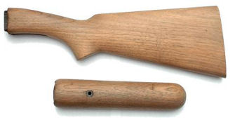
Refinishing the Wood
The butt stock and forearm had a few dings and scratches in
them along with 70+ years of age. I wanted to steam out the
dents and generally refinish the wood. I removed the butt
stock from the receiver and the forearm from the barrel.
The forearm had one screw holding the mounting hardware in
place so I removed the screw and mounting hardware.
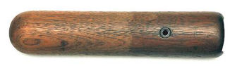
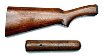
I used
Klean-Strip® KS-3 premium stripper I purchased from my
local home improvement store to strip the old finish from
the wood. This stripper is a thick paste which sticks to
the wood and doesn’t drip off. I applied the stripper with
a disposable brush and let it set for 15-minutes. I could
see the stripper start to work almost immediately. Then I
used paper towels to wipe off the stripper and the old
finish came with it. The above photo shows the forearm
before and after stripping. I performed the stripping
process three times to each piece of wood, then cleaned the
exposed wood with odorless mineral spirits as described in
the instructions. I was careful not to apply any stripper
to the inside of the forearm; I didn’t want to have to
refinish that area.
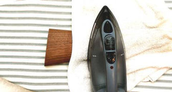
Once the
wood was stripped I applied a wet towel to the wood and
pressed a hot iron to the wet towel. This process steamed
out many of the dents, but also raised the grain. I could
not steam out some of the deeper dents and scratches, but as
my shooting friends say, that gives the wood “character”.
After the
wood dried I sanded the raised grain “feathers” with
400-grit sand paper until the wood was nice and smooth. I
applied some fast-drying polyurethane to the inside of the
hand guard and butt stock to help prevent moisture gathering
and causing rust.
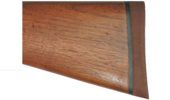
I decided
to leave the walnut its natural color. I followed the
finishing video found on the
Boyds’® gunstocks web site using
Birchwood Casey® Tru-Oil®. This process takes some
time, but the results are outstanding. I applied six coats
of Tru-Oil and sanded with 1,000-grit sand paper after the
third coat. I have always liked the smooth, semi-glossy
finish Tru-Oil imparts to the wood as you can see from the
above photo.
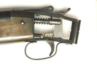
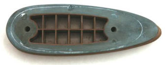
Repairing
the Auto Eject
At the time I lengthened the chamber and forcing cone I
removed the auto ejector parts so they wouldn’t become
damaged. The four parts involved in the auto eject
mechanism were 1) ejector, 2) ejector sear, 3) ejector
spring, and 4) ejector guide.
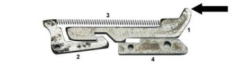
When the
barrel is closed the ejector (1) rubs against the breech
face causing it to be pushed inward until the notch in the
ejector clears the ejector sear (2) hook. The ejector
spring (3) being under tension causes the ejector sear (2)
to rotate so the hook falls into the notch. The hook at the
top of the ejector (arrow) is positioned under the rim of
the shell, and the shell is now fully seated into the
chamber.
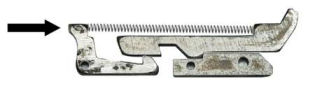
When the
barrel is opened and starts to swing forward the ejector is
still locked in place by the ejector sear. As the barrel
continues to swing forward the lobe on the front of the sear
(arrow) contacts the bottom of the notch cut into the barrel
hinge pin causing the sear to rotate so the hook drops out
of the notch. The ejector spring causes the ejector to
spring forward until it is stopped by the ejector guide (4)
causing the shell to eject out of the chamber.
The
barrel hinge pin is either pressed or silver-soldered into
the receiver so it cannot rotate. A notch is milled into
the center of the pin to accommodate the lobe on the front
of the ejector sear. The pin is installed so the notch is
at an angle to trip the ejector sear when the barrel is
opened.
On my gun
as the barrel was swung open, because the ejector was under
spring tension, the ejector was constantly rubbing against
the breech face and would open slowly. This allowed me to
pull the empty hull out of the chamber manually, but the
ejector would not snap open.
I
installed each part individually to make sure it moved
freely and found that the ejector sear was binding and would
not pivot. I polished the edges with 400-grit wet/dry sand
paper, and polished the ejector sear pin so the ejector
would rotate freely. I then installed the ejector, ejector
sear, and ejector guide without the spring to see how they
all worked together. After polishing the ejector sear and
pivot pin everything worked as it should. I lubricated and
reassembled the parts with the spring and now everything
works as it should.
Lightening the Trigger Pull
Although the trigger was crisp, it was very heavy. I
decided to lighten the trigger pull by replacing the trigger
return spring.
This
spring has a specific diameter to fit into a recess in the
frame to prevent it from slipping, and a specific length to
ensure the trigger spring guide rod stays in contact with
the trigger. This constant contact keeps the hammer back so
the firing pin does not protrude from the face of the
receiver to prevent loading or ejecting a shell.

New Spring (bottom)
I didn’t
want to cut the original trigger return spring because I
couldn’t find a factory replacement spring or guide rod in
the Numrich catalog or exploded diagram, so I decided to
replace it. Again I believe this was an early production
model because none of the diagrams I found had the long
trigger return spring and guide rod. I never throw away a
spring; you never know when you might need one to fix
another gun. I cut a piece of 0.231” OD spring from
Brownells spring kit No. 71
#025-071-000 three coils beyond the length of the guide
rod. This lightened up the trigger pull to 5 1/4 pounds.
You can see that the new spring is made of a narrower gauge
wire and is one coil shorter which makes it lighter than the
original.
Summary
This was
a fairly easy project. Most of the modifications I performed with hand
tools. Although I used a drill press to drill and tap the
bead hole, I could have accomplished this with a hand
drill. I now have a 1930’s era shotgun modernized for the
21st century. Just for fun, I may remove the
fiber-optic bead and install a flush-mount choke tube and
use this gun for cowboy action shooting.
|