Fabricating
a Custom Front Sight
by Roy Seifert
Click here to purchase a
CD with this and all Kitchen Table Gunsmith Articles.
Disclaimer:
This article is for entertainment only and is not to
be used in lieu of a qualified gunsmith.
Please defer all firearms work to a qualified
gunsmith. Any loads
mentioned in this article are my loads for my guns and have
been carefully worked up using established guidelines and
special tools. The
author assumes no responsibility or liability for use of
these loads, or use or misuse of this article.
Please note that I am not a professional gunsmith,
just a shooting enthusiast and hobbyist, as well as a
tinkerer. This
article explains work that I performed to my guns without
the assistance of a qualified gunsmith.
Some procedures described in this article require
special tools and cannot/should not be performed without
them.
Warning:
Disassembling and tinkering with your firearm may
void the warranty. I
claim no responsibility for use or misuse of this article.
Again, this article is for entertainment purposes
only!
Tools
and firearms are the trademark/service mark or registered trademark
of their respective manufacturers.
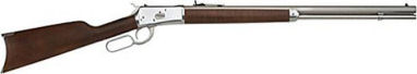
Navy
Arms 1892
My long-time shooting buddy, Jon (a.k.a. “Lone Star”) has
a beautiful stainless steel Navy Arms replica of a
Winchester
1892 in .45 Long Colt caliber with a twenty-inch octagon
barrel. He
recently installed a tang peep sight which he uses as a ghost
ring by removing the aperture.
Unfortunately, he couldn’t get the new sight low
enough, which meant the rifle was shooting high.
It was alright for “minute of cowboy”, but he
wanted to be able to adjust the sights to hit to point of aim.
Since the peep sight couldn’t go any lower, that
meant we would have to raise the front sight.
The rule is; move the rear sight in the same direction
you want the bullet to go, move the front sight in the opposite
direction you want the bullet to go.
I have a
number of spare sights in my parts bin, but none of them would
fit. Apparently
Navy Arms used a non-standard dovetail that was wider than
3/8. Jon also
mentioned that he didn’t necessarily need a beaded front
sight. So I
decided to fabricate a square post front sight for him using
my MAXNC 10
CL CNC hobby mill.
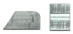
Fabrication
I ordered a 1/8” x 3/4” x 12” piece of steel bar stock
from OnlineMetals.com,
my favorite place to purchase metal.
This would become both the base and front post for the
new sight.
I
used CorelDRAW® to design
the pattern for the sight base and post.
I like using CorelDRAW® because I have greater design
control, and I am very fluent in its use.
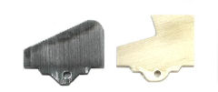
In the above figure the square in the middle of the
base is for the notch that will hold the post.
Now
for some math; I used my Front
Sight Height Calculator to calculate the increase in front
sight height. Jon
needed to move his shots down 6-inches at 25-yards.
The increase in front sight height would be 0.170
inches. His front
sight measured 0.328” which meant the new sight would have
to measure 0.498”; which we rounded up to 0.500”.
His base measured 0.515” wide and the dovetail was
0.389” wide (much wider than a standard 3/8” 0.375”
dovetail) and the base thickness measured 0.113”.
0.500” – 0.113” = 0.337” which would be the
height of the new front post.
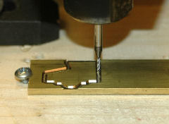
I also milled a notch in the base which allowed me to
keep the post straight when silver-soldering it to the base.
I wanted
the total height of the sight to be 0.500”.
Since the dovetail was 0.113”, that meant I needed
the front post to be 0.337” in height.
Remember, sight height includes the thickness of the
dovetail. Using
these measurements I created the machine “G” code for my
hobby CNC mill.
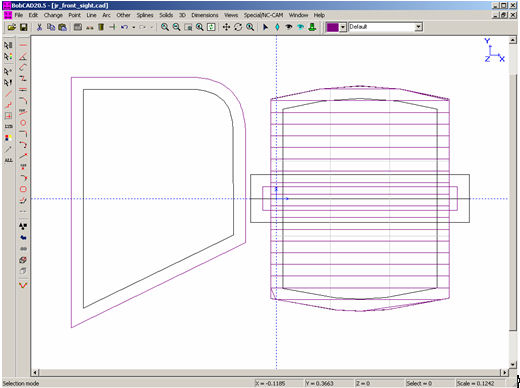
I exported
my design as a drawing .dwg file, which I imported into my
CAD/CAM software BobCAD-CAM.
I planned to perform the milling with a 1/16-inch
square end bit, so I created the tool paths offset by 0.0313,
or half the diameter of the 1/16 bit.
The purple lines in the above figure are the tool paths.
For the post and base the tool path was offset to cut
outside; for the notch in the center of the base, the tool
path was offset to cut inside. The multiple lines
on top of the base were for milling the thickness of the base
down to 0.113".
Assembly
After the parts were milled they had some rough edges.
I took a flat jewelers file and some 400-grit wet/dry
sand paper to trim the flashing.
I used a Cratex bit and my high-speed rotary tool to
polish the sharp edges on the base.
Now I
assembled the two pieces by silver-soldering them together.
First I cleaned each surface to be soldered, held the
part with a pair of needle-nose pliers over a propane torch,
and when the metal got hot enough, tinned the mating surface
with the solder. The
part needed to be hot enough so the solder would melt, flow
and stick; if the part was too hot the solder would bead up
and run off, if too cool the solder wouldn’t melt.
While the solder was still molten I used a brush to
wipe off the excess solder.
Now that
each part was properly tinned I inserted the post into the
notch, held the parts together with pliers, then held the
assembly in the propane flame so the solder on the parts would
melt and hold them together.
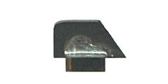
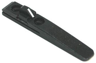
I also ran a bead of solder along the joint so it would
flow down into the seam. You
can see the soldered seam in the above photo.
The metal turned dark when I applied heat to the
pieces. I allowed
the assembled sight to cool to room temperature without
artificial quenching. If
the part is cooled too quickly the silver solder can become
brittle and the part could come apart.
After the sight cooled I took a flat jewelers file and
removed the excess solder from the corner of the joint.
Milling
the Dovetail Angles
So now I
had an assembled sight, but the base was square; I still
needed to mill the angles for the dovetail.
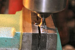
I mounted the sight upside-down in my machinist vise on
my table-top mill. I
installed a 65-degree dovetail cutter I purchased from Brownells,
set the depth so the bottom of the cutter was riding on the
bottom of the post, then ran the cutter along the front edge
of the base thereby cutting the correct dovetail angle.
I cut the rear edge the same way.
Final
Finish
The sight was still discolored by the heat from the soldering
process, so I took the sight to my blasting cabinet and
beat-blasted it clean. The
bead blasting removed the discoloration and left an even, matt
finish.
Now the
sight was ready to be blued.
I’ve had great success using Van’s
Instant Gun Blue. This
is the best, and probably most difficult cold-bluing product
to use. It really
isn’t very “instant”!
This product produces the closest result to hot bluing
and I’ve discovered it is the best product to use for bluing
larger areas. Using
vinyl gloves so my bare hands wouldn’t touch the sight, I
thoroughly degreased the sight using acetone.
I poured some Van’s Instant Gun Blue into a small
aluminum pan and immersed the sight into the solution so that
it was completely covered.
After 5 minutes I removed the sight.
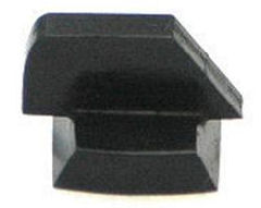
As you can see in the above photo the sight came out
with a deep, rich, even blue/black color.
I wiped the sight clean and coated it with gun oil to
stop the bluing process and to protect the sight.
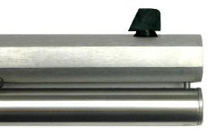
I
used a 65-degree dovetail file to fit the new sight into the
dovetail on the barrel. Notice
how high the post sits above the barrel.
This was because I measured the thickness of the
original sight base instead of the dovetail in the barrel.
Marlin®
39A
Jon’s sight came out so well I decided to make one for my
Marlin® 39A .22 lever-action rifle.
Like Jon’s rifle, this rifle came with a bead front
sight which I wanted to replace with a square post.
Jon uses his rifle for Cowboy Action Shooting™ so he
couldn’t have any color on his sight.
On my sight I decided to put a vertical white line
which seems to be popular for ghost-ring sights.
Brownells
sells a post front sight with a white line in the center for
$30. Using parts I
had on hand mine cost much less.
I used the 1/8” x 3/4” x 12” piece of steel bar
stock for the post as I did with Jon’s rifle.
Brownells sells a 12-inch piece of 3/8” dovetail
blank which I used as the base; this way I didn’t have to
cut the dovetail angles.
The
dovetail for Jon’s rifle was cut into the barrel.
Barrel-mounted front sights use a longer dovetail;
Jon’s measured 0.538”.
The front sight for my Marlin® 39A was mounted to a
ramp. Barrel ramps
still use a 3/8” dovetail, but with a shorter length.
My Marlin® front sight measured 0.437”.
The thickness of the base measured 0.087”.
Since I was cutting the base from 0.125” thick
dovetail stock, the depth of the notch needed to be 0.038”.
The total height of the sight was 0.265” so the post
was 0.178” high.
I again
used CorelDraw® to design the front post, then exported the
pattern to my CAD/CAM program.
I used my hobby CNC mill to cut a channel in the base
for the post, and to cut out the base from the dovetail blank.
I also used the CNC mill to cut out the post from the
1/8-inch bar stock. I
silver-soldered the post into the channel I milled in the
base, then milled a 3/64 groove in the front ramp of the post.
I bead-blasted the new sight, cold-blued it as
previously described, then applied white appliance touch-up
paint to the groove.
The
dovetail base was just slightly larger than the dovetail in
the barrel ramp. I
used my 65-degree dovetail file to file one side of the sight
base until it fit. The
top of the base is higher than the top of the ramp, but the
base of the post sets on top of the ramp with no unsightly
gap.
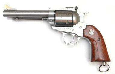
Ruger®
Bisley Blackhawk®
My Ruger® Bisley Blackhawk® required a higher front sight.
Since the original front sight was 1/8“ thick, I
fabricated my own, higher front sight blade.
Instead of using steel and bluing the sight, I
fabricated it out of brass.
Refer to my article Fabricating
and Installing a Taller Front Sight for a Ruger® Bisley
Blackhawk®.

I again
used CorelDRAW® to design the pattern for my new front sight
blade. The height
was 0.495” but I designed it with an undercut front to
reduce glare, rather than a post or ramp.
I purchased
a piece of brass 1/8” x 3/4“ x 12” from OnlineMetals.com.
I decided to fabricate the new blade out of brass
because it’s easier to work with.
I realize that since brass is softer than steel the new
blade could get deformed easier, but I’ve had steel blades
get deformed by being knocked around, plus I can always make a
new one. I’m
really not that hard on my guns so the brass blade should be
just as durable as a steel one.
Plus, I don’t have to worry about finishing the
brass. However, I
could, if necessary, produce a blade made of steel using the
steel bar stock instead of brass.
I took the piece of brass, mounted it to a piece of
wood on my milling table, and milled out the new blade.
After I
milled the new blade I touched up the sharp edges with a
jeweler’s file and installed it in the front sight base.
I took a 1/16” drill bit and using the hole in the
sight base as a guide, drilled the roll pin hole in the new
blade. After I
drilled the hole I installed the roll pin.
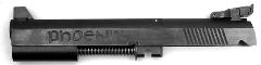
Tactical
Solutions 1911 .22 Conversion Kit
I have a 1911 .22 Conversion Kit that I purchased many years
ago. This was the
same kit on which I installed a fixed ejector, refer to my
article Resurrecting
a 1911 .22 Conversion Unit.
This kit is currently manufactured by Tactical
Solutions which comes with an adjustable rear sight, but
my original kit had fixed sights.
In order to prevent the hammer from hitting the rear
sight I had to install a high profile Millett
adjustable sight which they no longer manufacture.
That meant I would also have to install a higher front
sight.
My
measurements for this new front sight were as follows:
Bar stock
thickness: 0.123”
Dovetail depth:
0.085”
Dovetail width:
0.330”
Dovetail length:
0.452”
Height of post:
0.360” as measured from the top of the slide to the
top of
the post.
Width of notch:
0.123”
Depth of notch:
0.123 – 0.085 = 0.038”
Final height of post: 0.085
+ 0.360 = 0.445”
I
followed the same procedure as I did for Jon’s rifle using
the above measurements to fabricate the base and post.
The above photo shows the installed taller front sight.
Summary
With the proper tools and materials I can now fabricate custom
front sights pretty much made to order.
I think the next time I fabricate a custom front sight,
I will mill the base so it is the proper thickness, then mill
a notch for the post. I
would mill a tab on the bottom of the post that would set in
the notch. I still
like the channel because it helps me to get the post soldered
straight. In fact,
if I made the notch deeper I could attach the post in the same
way some front sight posts are attached to a 1911 slide.
|