Customizing a Kimber Pro Carry HD II
by Roy Seifert
Click here to purchase a
CD with this and all Kitchen Table Gunsmith Articles.
Disclaimer:
This article is for entertainment only and is not to
be used in lieu of a qualified gunsmith.
Please defer all firearms work to a qualified
gunsmith. Any loads
mentioned in this article are my loads for my guns and have
been carefully worked up using established guidelines and
special tools. The
author assumes no responsibility or liability for use of
these loads, or use or misuse of this article.
Please note that I am not a professional gunsmith,
just a shooting enthusiast and hobbyist, as well as a
tinkerer. This
article explains work that I performed to my guns without
the assistance of a qualified gunsmith.
Some procedures described in this article require
special tools and cannot/should not be performed without
them.
Warning:
Disassembling and tinkering with your firearm may
void the warranty. I
claim no responsibility for use or misuse of this article.
Again, this article is for entertainment purposes
only!
Tools
and firearms are the trademark/service mark or registered trademark
of their respective manufacturers.
Click on any blue text to go to
a product/seller web site.
Introduction
I received a very nice bonus at the end of 2015 so of course
I bought a new gun! When I was in high school I was a
member of the school rifle team. Our faculty advisor owned
a Colt 1911 in .38 Super and allowed us to shoot it if we
bought the ammo. That was the first handgun I ever fired
and I have wanted to add a .38 Super to my collection.
I have a
number of full-size 1911’s in my collection in .45 ACP, 9mm,
and .22 LR, but I wanted one in stainless steel, .38 Super,
and Commander length. To build one from parts would have
cost me about $1,500 and over 60 hours in labor so I started
to search the Internet to see if I could find a commercially
made model that fit my specifications. I finally found and
purchased a Kimber Pro Carry HD II.
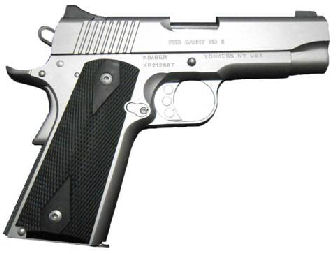
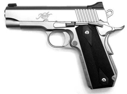
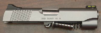
Kimber
Pro Carry HD II
Kimber has developed an excellent reputation in the 1911
market and has many models to choose from. The Pro Carry
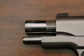
series of pistols have a 4-inch bushingless barrel which
makes them 1/4-inch shorter than a standard Commander-length
pistol. The barrel is flared at the end so the barrel
opening in the slide is wedged against the flare when the
slide is in battery.
The
series II has a firing pin block that is released by the
grip safety rather than by the trigger bow as in a Colt
Series 80 so it does not affect the trigger pull. Many
shooters with series 80 guns remove the firing pin block
because of how it affects the trigger, but I will keep mine
in place.
My
research indicated that the HD may stand for “heavy duty”
because the frame is all steel instead of aluminum alloy,
and in fact mine is all stainless steel with a nice matte
finish. The gun came with molded rubber grips which seemed
to enhance my grip on the gun, fixed Novak-style sights, and
one magazine that holds 9 rounds. This production pistol
was tight; there was no slide rattle on the frame, and the
bushingless barrel locked up to the slide perfectly which
enhances accuracy.
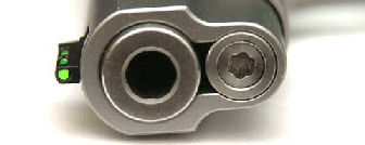
Because
the gun has a full-length recoil spring guide rod, to
disassemble the gun I had to lock the slide open, insert the
L-shaped takedown tool into the hole in the guide rod, then
release the slide. The tool keeps the recoil spring
compressed so I can remove the parts from the slide. I see
this as being problematic in the field since I may not have
that tool available.
My only
dislikes were the fixed sight, the need for the takedown
tool, the trigger shoe was too long for my hand, and the
trigger had just a bit of creep. Other than those minor
squawks, this gun was ready to go right out of the box.
Because the firing pin block is connected to the grip safety
I had to be sure I kept my hand off of that safety when
removing or installing the slide onto the frame, otherwise
the push rod would interfere with the travel of the slide.
Customization Plan
Although this gun was ready to go right out of the box, I
wanted to make a few modifications of my own. Most of these
modifications wouldn’t really improve the gun but just my
personal preferences. My modifications would be to:
-
Increase the secondary angle on the sear to remove the
creep
-
Replace the trigger with a medium-length trigger
-
Adjust the trigger for pre-travel and over travel
-
Checker the front strap
-
Install a bobtail mainspring housing
-
Checker the bobtail mainspring housing
Because
I’m going to take a file to my new gun this will probably
void Kimber’s excellent warranty. However, this really
doesn’t bother me since I can replace/repair most problems I
encounter with a 1911 pattern pistol.
Removing
Creep
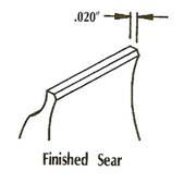
The
trigger pull on this gun really wasn’t bad; it broke cleanly
at 5 pounds but had just a little bit of creep. When I
examined the sear it looked like it had a very small
secondary angle; the width of this angle should be 0.020”.
I installed the sear into my Marvel 1911 Sear/Hammer Jig
#080-823-000 and following the instructions that came
with the jig, used a medium-fine ceramic stick
#080-721-604 to increase the angle. The trigger is now
nice and crisp with no creep and breaks at exactly 3-pounds.
Replacing
the Trigger with a Medium-Length Trigger
My hands are not very large so I don’t like having to
stretch to get the first pad of my trigger finger on a long
trigger. Fortunately,
Nighthawk Custom sells short, medium, and long length
adjustable triggers. I purchased a medium-length adjustable
trigger
#333149 from
MidwayUSA.
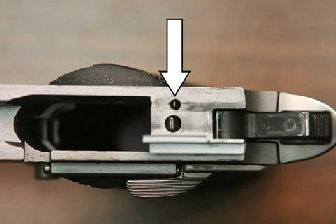
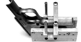
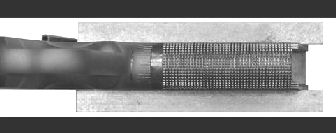
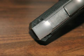
This was
not quite a drop-in part; it required some fitting. To get
the trigger shoe to fit in the frame I had to polish the top
and bottom as shown by the white arrows in the above photo.
I only had to rub the top and bottom faces across 400-grit
wet/dry sand paper about 20 times to get the trigger to fit
and move smoothly with no up or down movement. This results
in a consistent trigger pull.
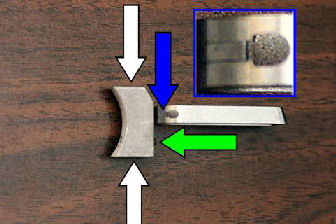
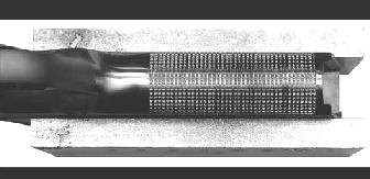
Adjusting
Pre-Travel and Over Travel
The trigger came with pre-travel adjustment tabs as shown by
the blue arrow and enlarged inset in the above photo. There
was one tab on each side of the trigger bow. To adjust
pre-travel, I bent the two tabs out just a bit and
reassembled the gun. With the hammer in the half-cock or
safety notch position the trigger should not move. If the
tabs are bent too far out the grip safety will no longer
function.
The
trigger came with an over travel adjustment set screw shown
by the green arrow in the above photo. I installed the set
screw into the trigger with Loctite blue. To adjust over
travel, I turned in the screw until the safety notch on the
hammer just touched the sear when it fell, then backed the
screw off 1/8 turn. This was a trial and error process; the
steps are as follows:
-
Cock
the hammer.
-
Turn
in the over travel adjustment screw 1/4 turn.
-
Hold
the hammer with two fingers, pull the trigger, and allow
the hammer to gently fall.
-
Repeat steps 2 and 3 until the safety notch on the
hammer just touches the sear when the hammer falls.
-
Back
off the adjustment screw until the safety notch no
longer touches the tip of the sear when the hammer
falls; over travel is now adjusted properly.
Checkering the Front Strap
I like the positive grip that a checkered front strap
provides. I purchased a 20 lines-per-inch checkering file
#080-310-401 and the Marvel Precision 1911 Auto EZ
Checkering Fixture
#588-100-011. The checkering fixture is an expensive
tool, but ensures I get nice straight lines.
I
completely stripped the frame and installed the fixture onto
the grip screw bushings. Following the included
instructions, I set up the fixture to make the relief cut in
the frame. The relief cut serves as the border for the
checkering and allows me to take full strokes with the
checkering file.
I used
the 3/16 file that came in the Kart Precision Barrel XAct
Fit Tool Kit
#472-015-000 to file the border about 0.030” deep. I
could have used a flat jeweler’s file instead of the Kart
file. This left a sharp edge at the top of the border
underneath the trigger guard which I will file/grind smooth
after I finish the checkering.
I reset
the fixture to make the vertical cuts. I installed a
plastic tie wrap in the border to prevent the file from
moving too far, and covered the exposed trigger guard with
three layers of masking tape. This prevented me from
scratching the frame in case my file slipped. I rotated the
jig around the circumference of the front strap and cut the
vertical lines. I cut until the file skidded along the
metal and wouldn’t cut anymore. This process takes hours to
complete and should not be rushed. “Patience is a virtue”
as they say.
Notice in
the above photo how I scratched the front strap of the frame
under the trigger guard. I had to remove the cable tie to
get nice, even lines. These scratches will be removed when
I blend and polish the sharp edge of the border.
After the
filing was completed I used a small, triangular file to
clean up each line. I was careful not to allow the file to
skip across a line.
I set up
the fixture to make the horizontal cuts and cut down the
length of the front strap. I again cut until the file would
not cut any more. As I moved the fixture down the frame I
was sure to keep the file lined up with the prior cuts.
After
cutting the horizontal lines I again cleaned them up with a
small triangular file. I coated the checkering with a blue
marker and went over all the horizontal and vertical lines
once more to ensure they were all even.
I used my
6-inch narrow pillar file
#191-400-760 and filed a border on the bottom of the
frame. I wrapped some 400-grit wet/dry sand paper around
the file and polished the border until it was smooth and all
filing marks were removed.
I then
used my Dremel tool and a fine sanding drum to smooth the
top ledge of the border under the trigger guard, then used
400-grit wet/dry sand paper and “shoe shined” under the
trigger guard to remove and smooth out the grinding and
filing marks.
Finally,
I put the frame in my bead blaster and blasted it with
glass-bead media to get the same matte finish as the
factory. This process also dulls the sharp points of the
checkering just a bit so they don’t dig into my hand so
much.
Checkering the Bobtail Mainspring Housing
To make
this gun more carry friendly I wanted to round the bottom
rear corner of the mainspring housing and frame. I had
never performed this process before and wanted to add it to
my skill set. I purchased an Ed Brown smooth, stainless
steel bobtail mainspring housing
#168206 and installation fixture
#259442 from MidwayUSA. The smooth housing came with
all the internal parts, and was $25.00 cheaper than the
checkered version.
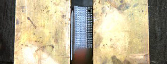
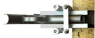
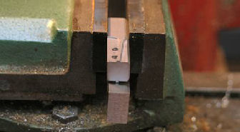
I wanted
the new housing to be checkered like the front strap of the
frame. It was cheaper to do the checkering myself than pay
for a factory checkered one. I installed the mainspring
housing in my vise and used the bronze jaws as a guide to
file the lines. I cut the first set of lines using my 20
LPI checkering file with the housing deep in the jaws as
seen in the photo above. After the first set of lines were
cut I positioned the mainspring housing above the jaws and
finished the vertical lines. The first set of lines acted
as a guide for the rest of the vertical lines.
I
repositioned the mainspring housing deep in the jaws so I
could again use the jaws as a guide to file the first set of
horizontal lines. I then moved the file over 5 lines to cut
the next set of lines. You can see the result in the above
photos.
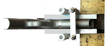
Installing the Bobtail Mainspring Housing
There are a couple of videos on
YouTube showing how to install the bobtail mainspring
housing. Installation requires drilling a new mainspring
housing retaining pin hole and reshaping the frame and
grips. The instructions say to install the fixture into a
vise, center a 5/32” drill bit in the top hole (this will be
the location of the new retaining pin hole), insert the
frame onto the fixture, lock it place with the retaining pin
in the bottom hole, then drill the new hole. The hole
should be started with a center drill, then completed with
the 5/32 drill bit. The center drill has a thick shaft
which prevents the bit from wobbling and wandering when
drilling the smaller pilot hole. If not done properly the
drill bit will wobble and/or wander and the hole will be
off-center or oval in shape. One of the YouTube videos I
watched showed how the user ovaled the hole because he
allowed the bit to wobble, then he had to weld up the frame
to correct his mistake.
I don’t
have a center drill, although they are available on ebay at
fairly inexpensive prices. Without a center drill, there
are a few methods I can use to prevent the bit wobble
problem:
-
Install the drill bit deep into my chuck to prevent it
from wobbling. The shorter the length of the bit, the
less chance for the bit wobble and wanter.
-
Plunge-mill the hole with a 5/32” square end milling
bit. I would only be able to mill one side, then use a
5/32” drill bit to finish the other side. The fixture
would act as a drill guide for drilling through to the
other side of the frame. This is the method I
ultimately used.
-
Install the fixture on the outside of the frame to use
as a drill guide for the first hole. One YouTube video
showed this method, but I would be concerned about not
getting it aligned properly and being able to hold the
jig in place.
I
installed the fixture horizontally in my machinist’s vise
and leveled it with a parallel. Because the fixture was not
in the center of the vise jaws I had to tighten the vise
very hard to prevent the fixture from moving. Yup, I
learned this the hard way when the fixture rotated under the
pressure of milling the first hole, and I had to stop and
set everything up all over again! Fortunately it didn’t
mess up the hole.
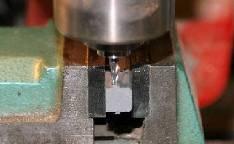
I
installed a 5/32 square end milling bit and centered it in
the top hole. This was a carbide, center-cutting bit so I
could plunge mill the hole.
I
installed the frame onto the fixture and held it in place
with the hammer pin. The hammer pin is the same diameter as
the mainspring housing retaining pin, but the hammer pin has
a lip that prevents it from falling through the hole.
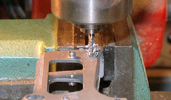
I
plunge-milled the first hole with the 5/32 square end bit.
I used very light pressure on the mill because I wanted the
bit to cut and not bind or wander. The bit cut through the
frame as if it were butter.
After the
hole was milled I removed all the internal parts from the
new bobtail mainspring housing and installed it in the frame
to ensure the new hole in the frame would line up properly.
I had to ream the new hole with a #21 drill bit to get the
pin to fit, but it was lined up properly.
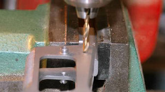
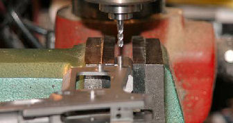
I
reinstalled the frame onto the fixture and locked it in
place with the hammer pin as before. I centered a #21 drill
bit in the top hole and drilled completely through the
frame. The fixture acted as a guide so the drill bit
wouldn’t wobble. The mainspring housing retaining pin fit
perfectly through the new holes in the frame and in the
bobtail mainspring housing.
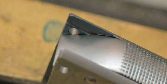
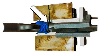
The
inside of the frame that I planned to cut off I painted with
a blue marker. I reinstalled the internal parts into the
mainspring housing and installed the housing onto the frame
with the retaining pin. I took a sharp scribe and scribed
around the mainspring housing. This mark, which you can see
in the above photo, told me where to stop cutting the frame.
I used my
Dremel tool and a cutoff wheel to cut the corners. I
installed the mainspring housing in the frame and installed
the retaining pin. I used my Dremel tool with a fine
sanding drum to shape and contour the sides to the bottom of
the mainspring housing. I didn’t mind grinding into the
housing since I was going to finial polish the frame and
housing anyway.
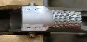
Once this
was done I used strips of 400-grit wet/dry sand paper and
“shoe shined” the back of the mainspring housing and edges
of the frame until they were smooth and no grinding marks or
divots were present. I then bead-blasted the polished metal
to match the rest of the finish on the frame.
If you
look at the above photo you can just barely see two small
divots at the bottom of the frame where it meets the new
mainspring housing. These were what was left of the
original retaining pin holes. The original holes were a bit
farther in from the rear edge of this particular frame which
left the two divots. I don’t know if this is the same for
all Kimber frames, or just my frame. On a standard 1911
frame these small divots would not exist after blending the
frame to the bobtail mainspring housing because the holes
would be closer to the rear edge of the frame.
I trimmed
the rubber grips to allow for the cut in the frame and the
new location of the mainspring housing retaining pin. The
above photo shows the results. The grip feels a bit strange
in my hand because it is shorter, but this doesn’t seem to
affect the handling characteristics. The gun is very
comfortable to carry, because there is no corner to stick
into my side. Overall I am pleased with the modifications I
made to my Kimber Pro Carry HD II, but again, I have
probably voided any warranty that came with the gun.
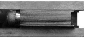
Failure
to Feed
I put together some dummy rounds so I could test the
function of the pistol. To my surprise I got a failure to
feed. After successfully feeding a round 3 or 4 times, that
same round got jammed under the extractor and would not
allow the slide to go into battery.
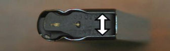
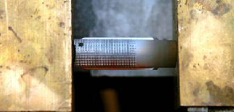
When I
examined the cartridge I found it had sharp grooves cut into
the rim of the case. These grooves were catching on the
extractor hook which prevented the round from feeding. I
discovered this was caused by the sharp edges on the feed
lips of the Kimber magazine as shown in the above photo.
I pushed
the follower down into the magazine with a pencil and held
it in place with a pin pushed through one of the holes in
the side of the magazine body. I took a narrow 220-grit
stone and stoned off the sharp edge. I then took my Dremel
tool with a Cratex bit to finish rounding and smoothing the
edges. Prior to doing this I couldn’t remove the first 3
rounds from the magazine with my hand. Now the cartridges
slip easily out of the magazine. I purchased a second .38
Super magazine manufactured by Mec-Gar and found their feed
lips were already rounded and smoothed.
Addendum 04/08/2020 Corona Virus Shelter In Place Project
Replacing the Front Sight
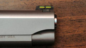
I purchased a Hi Viz #KB2015 fiber-optic front sight from
Amazon.com to replace the blue steel sight.
I am a big fan of light-pipe sights because they are
easier to see against a dark background.
I used a brass punch and “removed the sight from left
to right”. I
removed the light pipe and installed the sight onto the slide
from right to left.
The new sight fit perfectly.
The sight came with 3 light pipes:
solid white, optic red,
and optic green. I
installed the green light pipe which I prefer.
Replacing the One-Piece Full-Length Guide Rod (FLGR)

I have been viewing with interest a series of YouTube videos
by 18echosf (Adrian) on how he replaced the FLGR on his Kimber
Pro Carry II with a commander-length guide rod.
In his first video he explained he was doing this was
because he didn’t like having to use the Kimber L-tool to take
down the gun when in the field.
https://www.youtube.com/watch?v=ZSne_GWjB4Y
By the way, a bent
paper clip will work in place of the L-tool, but again, who
carries the tool or paper clips to the range where they can
get lost?
Eventually Adrian decided to go back to the Kimber full-length
guide rod because he found the Wilson and Colt
commander-length guide rods were peening the inside of his
frame.
https://www.youtube.com/watch?v=RUotr1VgcPU&t=21s
He discovered that the head of the short recoil guide
was narrower than the Kimber and was causing the peening.
Personally, I think he’s going to get the peening
regardless of what spring guide he uses because he has the Pro
Carry II model which has an aluminum frame.
I have the Pro Carry HD II model which has an all-steel
frame, so I don’t think I should get this peening problem.
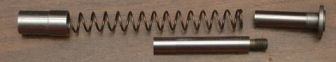
Disassembling the Kimber Recoil Spring and Guide Rod Assembly
I decided to install a two-piece full length guide rod.
I used the original Kimber recoil spring and reverse
plug, but I first had to disassemble the Kimber recoil spring
and guide rod assembly.
Hobbygarage619 sells a set of tools on ebay for disassembling
the Kimber.
https://www.ebay.com/p/1046107556?iid=202476500431#viTabs_0
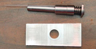
I made a disassembly tool by cutting a piece of 1/4” aluminum
and drilling a 15/32” hole in the middle.
Ok, so I can’t cut a straight line with a hack saw;
this is not a precision tool!
The hole was not quite wide enough to slip over the reverse
spring plug, so I took a Dremel tool with a 3/8” sanding disk
and opened the hole until it would just fit.
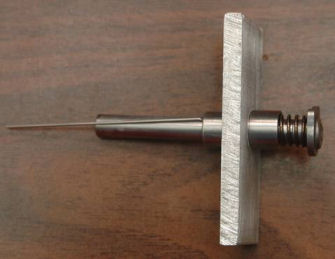
I placed the tool over the spring plug as show in the
above photo, placed the wide rear of the guide rod in the heel
of my hand, placed the fingers of that hand over the tool and
pressed down until I could remove the L-tool, then carefully
released the spring tension.
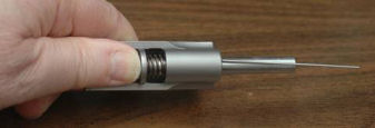
The other method is to install the assembly in the slide,
press against the head of the recoil rod with your thumb until
tension is released from the L-tool, remove the L-tool, then
carefully release the spring tension.
Putting it back together with your thumb can be a
painful process, which is why I like to use the tool instead.
In my stock of 1911 parts I had a Wilson 2-piece full-length
guide rod assembly that I had purchased from MidwayUSA.com
part
#136387. This
part was made for a full-length 1911 so it was a bit long for
my Kimber.

I marked the front of the guide rod and used my lathe to cut
off the excess. I
faced off the front and slightly chamfered the edge.
The Wilson two-piece full length guide rod (FLGR) had a
hex hole in front so it could be unscrewed with a hex key.
When I shortened the front, I removed the hole.
If I had been smart, I would have cut a slot so I could
use a screwdriver to unscrew the front, but no, I wanted to
get fancy!
I used CorelDRAW 12 to design a milling pattern, then exported
it to BobCAD-CAM v20 to create the G-code for my table-top CNC
mill. I used a
1/6” square end bit to mill the six holes, then used a 1/8”
square end bit to mill out the center.
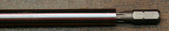
Because of the shape of the hole I now needed to use a T27
Torx bit to unscrew the rod for disassembly.
I think I’ve gone from the frying pan into the fire!
In my range bag I carry a small screwdriver kit I
purchased from Walmart that has Torx bits in it, so I should
be ok in the field.
I installed the spring onto the rear half of the guide rod,
installed the reverse spring plug in the slide, and installed
the spring/guide rod into the slide.
Notice how the spring is bowed in the above photo.
When installing the slide onto the frame I must hold
the spring against the slide to prevent it from binding.
With the slide installed in the frame I locked the slide open
with the slide lock.
I put a drop of Loctite blue on the threads and screwed
the front part of the guide rod onto the rear part.
To disassemble the gun for cleaning I first need to
unscrew the front part of the guide rod, then I can remove the
slide from the frame.
The debate on forums over short guide rods vs. one-piece
FLGR’s vs. 2-piece FLGR’s continues ad-nauseum.
Some 1911 shooters don’t like the 2-piece FLGR because
they sometimes come apart during heavy use.
The Loctite blue should take care of this problem but
will still allow me to disassemble the gun for cleaning.
In 2005 I took an online 1911 build course from the late Dave
Sample. He was a
proponent of the full-length guide rod.
I have built two additional 1911’s all with FLGR’s
based on what I learned in Dave’s class.
If they were good enough for Dave, they’re good enough
for me.
|