Building an Inductive Brass Annealer
by Roy
Seifert
Click here to purchase a zip file with this and
all Kitchen Table Gunsmith Articles.
Disclaimer: This
article is for entertainment only and is not to be used in lieu of a
qualified gunsmith. Please
defer all firearms work to a qualified gunsmith.
Any loads mentioned in this article are my loads for my
guns and have been carefully worked up using established guidelines and
special tools. The
author assumes no responsibility or liability for use of these loads,
or use or misuse of this article.
Please note that I am not a
professional gunsmith, just a shooting enthusiast and hobbyist, as well
as a tinkerer. This
article explains work that I performed to my guns without the
assistance of a qualified gunsmith.
Some procedures described in this
article require special tools and cannot/should not be performed
without them.
Warning: Disassembling
and tinkering with your firearm may void the warranty.
I claim no responsibility for use
or misuse of this article. Again,
this article is for entertainment purposes only!
Tools
and firearms are the trademark/service mark or registered trademark of
their respective manufacturers. Click on any
blue text to go to a
product/seller web site.

Introduction
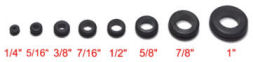
Shown in the above photo are the calibers for which I reload.
Firing and resizing work-hardens the
brass and shortens its life causing it to crack at the thinnest parts, the mouth
or neck. To prolong the life of
rifle brass it should be annealed.
Annealing is the process of heating the brass to make it softer so it will last
longer. I’ve never tried to anneal
my brass in the past, because I don’t shoot that often, but I decided to build
my own brass annealer.
There
are two primary methods to anneal brass; heat the brass in a flame from a
propane torch, or heat the brass with an inductive heater.
Inductive heating uses alternating current through a coil of wire.
The brass case is placed in the center of the coil and heated to a
specific temperature for a fixed length of time.
Only about the top 1/3 of the case needs to be annealed.
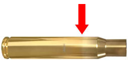
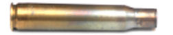
aled
at the factory by the manufacturer.
In the above photo you can clearly see the line where the top of the brass was
annealed. An Internet search brought
up a post on the
Sniper’s Hide Forum by Tim Sloper on how to build an inductive annealer
using parts purchased from Amazon. I
decided to copy his build, but I found the parts cheaper on ebay.
Some had to come from China to get the lower prices, but I don’t mind
waiting 2 weeks to get the best price.
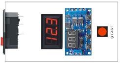
Inductive Annealer Parts
Here are the parts I purchased from ebay:
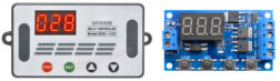
I
purchased the version that came with a case because it had longer push-button
actuators. I plan to mount the timer
board in a case using standoffs so I needed the longer actuators.
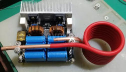
This
induction heating module came with an insulated coil of copper tubing.
The diameter of the coil was too large to use with brass cases which is
why I’m using the copper wire. I’ve
seen some homemade case annealers on the Internet that pumped water through the
copper tubing to keep it cool.
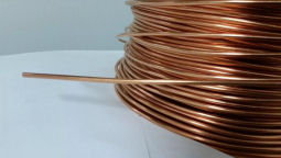
Ten
feet of wire was enough to make three coils.
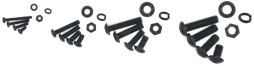
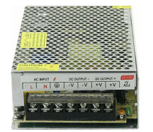
Because most of the parts came from China, they had to be mounted with metric
screws. The four holes on the bottom
of the power supply used M4 screws, and the four standoffs for the inductor used
M3 screws. I purchased a metric
fastener set from
Amazon that had the screws and washers I needed.
I
already had line cords for the power supply, a momentary push-button switch to
trigger the timer, and a plastic case which I will explain about later in this
article. I also had plenty of hookup
wire and terminal connectors for this project.
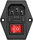
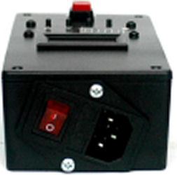
I had
an AC power socket I purchased from ebay that I used for another project.
I deactivated that project and recycled
the AC power socket for this project.
This socket comes with a lighted switch and a fuse.
I can keep the annealer plugged in and just use the switch to turn it on
or off.
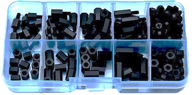
I
needed standoffs to mount the timer in my case
and
fan controller on the baseboard.
I had purchased a set of M3 nylon standoffs for another project, which
worked perfectly for this project.
Cutting Out the Panel
Long ago I had purchased a plastic case from Mouser.com
#546-1591XXDSBK that was large enough to house a digital volt meter, the
timer, the momentary push button, barrier strip, and AC power socket.
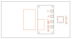
I laid
out the panel using CorelDRAW v12.
The case measured 6” x 3” so I started with a 6” x 3” rectangle.
I carefully measured all the components and laid them out on the
rectangle. Everything you see in
red in the above figure will be cut out using my
tabletop CNC mill. The words and
up/down symbols I’ll engrave with a 0.040” milling bit also with my CNC mill.
The large space on the left is to accommodate the AC power socket.
I
placed exact size photos of the internal components onto the drawing.
There needed to be enough space between the back of the AC power socket
and the volt meter for the AC wires and spade connectors connected to the AC
power socket.
I
exported the layout as a .dwg file which I imported into BobCAD CAM v20.
Once imported I created the G-code for my CNC mill.
I centered the lid of the case on the cross-slide table of the mill
and used a 3/32 end mill to cut out the holes.
I turned and moved the bit slowly because I didn’t want to melt the
plastic and bind or plug the bit.
After all the holes were milled, I used a 0.040” bit to engrave the letters and
symbols. I only engraved 0.010”
deep, I didn’t want to go completely through the lid.
After
I completed the milling and engraving, I melted a white wax crayon over the
letters. When the wax dried, I
scraped off the excess. I then
coated the panel with a mat clear coat to prevent the wax from coming out of the
letters.
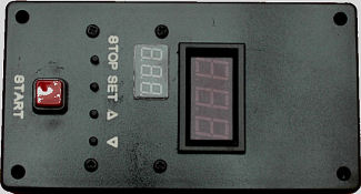
I
installed all the components in the panel and everything fit perfectly.
As they say, “measure twice, cut once”.
I actually measured about five times to ensure everything was correct.
The volt meter came with locking lugs to lock the meter into the panel,
but those broke off long ago. I used
some hot glue on the back edges of the meter to hold it in place.
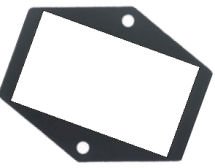
I
wanted to mount the AC power socket at an angle so it would fit on the end of
the case. I created a pattern with
CorelDRAW on plain printer paper, then cut out the pattern.
I taped the pattern to the end of the case and used a straight edge to
score the plastic around the edges of the center.
Notice how the pattern is tilted 20-degrees so two of the edges would be
parallel to the top and bottom of the case.
I used
my Dremel tool with a cutoff disk to cut out the square hole following the
scored lines. Because the tool spins
so quickly it has a tendency to melt the plastic.
I used a fine file to clean up the edges and remove the melted plastic.
With the AC power socket in place, I marked where to drill the mounting
holes. I used a 3/32 drill bit to
drill the mounting holes, then used sheet metal screws to mount the socket.
The socket fit perfectly; it is flush with the bottom and does not
interfere with the lid. The reason I
used the case was so I could mount the AC power socket and be able to leave it
plugged in.
Winding the Coil
Tim’s
post says to wind the coil no larger than 20mm in diameter.
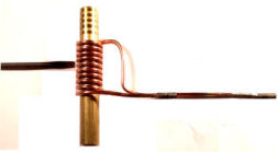
I wound the copper wire 10 turns around a piece of 5/8" brass rod.
This came out to 17mm in diameter.
After I wound the coil, I took a flat blade screwdriver to separate the
individual loops. Reading Tim’s post
his annealer is set up for .223 cases so his coil is 15mm – 16mm in diameter.
The larger the coil the more time it takes to heat the case.
I
trimmed the ends of the coil and bent one side so it would fit in the inductor
connectors. The copper wire was too
thin to fit under the screws so I removed the plastic insulator from two butt
connectors and soldered them onto the wire ends.
The photo above doesn’t look straight because of the angle of the camera
when I took the picture. I later
discovered the leads were too long!
I shortened the leads, removed the insulators from two #6 ring connectors,
spread the connector apart and soldered them to the leads.
Now I could screw the leads directly onto the standoffs on the inductor
board.
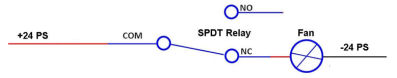
Connections
I
created a schematic of the connections I would need.
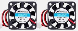
The only things not shown here are the 24v fans.
I’ll mount them in front of the two heatsinks on the inductor board and
the coil to keep them cool.
I have
a box of electronic components and parts.
In there I have two packages of rubber grommets I purchased long ago from
Radio Shack. Radio Shack no longer
sells these, but sets are available on Amazon and ebay.
I
drilled two 3/8 holes on the left side of the case for AC out and +24/GND in,
and one 3/8 hole on the right side for the timer output.
I installed 3/8 grommets into the holes which will protect the wires from
becoming frayed on the bare edge of the plastic holes.
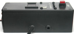
In the above photo you can see the AC line cord coming out of the case.
For
some reason I have many spare AC line cords.
One I will use to plug into an AC wall socket and the other end I’ll plug
into the AC power socket in the case.
I took another AC line cord and cut off the ends to expose the wires.
On one end I crimped female spade connectors, which I connected to the AC
power socket. The other end I
crimped U connectors which I connected to the power supply.
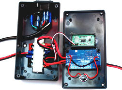
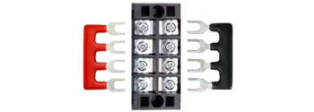
I
mounted a terminal block inside the case to connect the internal wiring.
The heavy black cable on the left is a line cord that carries AC from the
AC power socket to the power supply.
Notice how much space I had to leave to accommodate the connectors on the back
of the AC power socket. The red and
black wires on the left are +24 and -24 coming from the power supply to the
terminal strip. Although its hard to
see, the meter and the timer are connected to the terminal strip.
The red and black wires coming out of the right of the case go from the
timer to the inductor board to turn it on.
Rather
than running separate wires from the switch to the terminal strips on the timer
board, I soldered wires directly to the contact points on the back of the timer
board. I connected +24 to the
switch, then from the switch to the positive trigger input.
I connect a wire directly from ground to the negative trigger input.
Everything fits in the case.
Layout
As mentioned before, I decided to duplicate Tim’s layout with two changes.
The plastic case as mentioned before, and 24-volt fans to cool the
inductor board heat sinks and coil.
The 40mm fans I will wire directly to the power supply, the 120mm fan to a fan
controller
Building a Stand
I took some scrap wood I had in the garage and built a stand for the annealer.
I cut a 24” 2x4 in half making two pieces 12-inches long.
These are the legs for the stand.
I cut a piece of 1/4-inch hardboard into a 10” x 20” baseboard.
I laid the 2x4’s on their edge and screwed the hardboard onto the 2x4’s.
I
drilled holes and mounted all the components onto the stand with the appropriate
metric screws and washers. I screwed
the plastic case onto the stand by drilling holes through the bottom of the case
into the hardboard, then used #10 x 1/2 wood screws to hold it down.
I drilled a 3/8 hole in the stand to feed the AC line cord, and a
corresponding 3/8 hole in the leg below the power supply.
I fed the AC line from the case through the two holes and connected the
leads to the power supply. I
connected the +24 and -24volt wires to the output of the power supply.
I did not connect the inductor board.
Testing and Adjustments
I left
the inductor board disconnected until I figured out how to program the timer.
Once I had the timer programmed, I connected the annealer board.
I ifound that I only needed 7.6-seconds before the top of the
case just started to turn red. The
above photo shows my first annealed case.
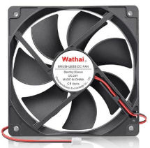
I also
discovered that the coil gets very hot.
I put the 24-volt 120mm fan I purchased from
Amazon.com behind the coil to cool it down.
I programmed the timer so that when triggered, the inductor stays on for
7.6 seconds, then there is a 45-second delay
to help cool the coil. The anneal/cool down cycle loops until the Start
button is pressed.
Installing the Fans
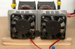
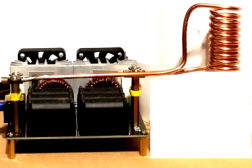
The
inductor board heatsinks were raised above the board so I couldn’t mount the
40mm fans directly on the board. I
glued 5 craft sticks together with wood glue, then glued the makeshift stand to
the board. I attached the fans to
the raised stand with hot-glue and added an extra drop of glue to the bottom
ends of each fan. In the above photo
you can clearly see the craft sticks and drops of hot-glue on each end of the
fans.
The
40mm fans came with connectors which I removed and added 5-inches of wire to
each lead. I soldered the ends of
the fan leads to the extensions, then protected the solder connection with
heat-shrink. I crimped U-connectors
to the other ends of the extensions.
I attached the U-connectors to the appropriate connectors on the power supply.
Now the fans come on when I turn on the AC.
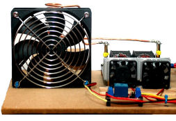
I
mounted the 120mm fan behind the coil.
I drilled holes in the baseboard and fixed the fan with tie wraps.
I used nylon 3mm standoffs to mount the fan controller to the baseboard.
I cut the wires so they would reach the output of the fan controller.
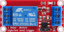
I
wanted the 120mm fan to come on only when the timer was off so it would cool the
coil. I didn’t want to cool the coil
when annealing a case. I connected
the black fan wire to power supply -24v and the red fan wire to the normally
closed relay contact. I connected
+24v from the power supply to the relay common contact.
The
way this is wired, as soon as I turn on AC, the 120mm fan comes on.
When the relay is energized power is removed from the fan and the fan
shuts off during the annealing process.
When the annealing is finished after 7.6-seconds, the fan comes on to cool
the coil.
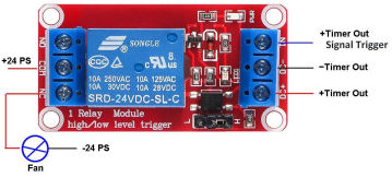
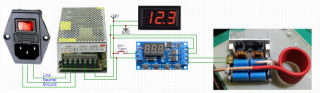
I
discovered that when the timer is off, both of the timer outputs are at
+24-volts. I connected the negative
timer output to the DC- input of the fan controller.
I connected positive timer output to both the fan controller DC+ and
trigger in as shown in the above figure.
When the timer is off, both the positive and negative inputs to the fan
controller are +24v so the relay is de-energized which allows +24v to be routed
to the 120mm fan. When the timer is
on, the negative output of the timer goes low, the trigger stays at +24v
allowing the relay to turn on and removing +24v from the fan.
When the timer shuts off, the cooling fan comes on to cool the coil.
I was afraid the fan would blow over the case inside the coil, but the
case didn’t move.
Height
Adjuster
Because I planned to anneal different lengths of cases I wanted a means to
adjust the height of the case inside the coil.
I cut four pieces of 1/4” S4S poplar board I had left over from another
project into 7.875” x 3/4” and glued them together to make a 1-inch platform.
I drilled a 1/4” hole in the end.
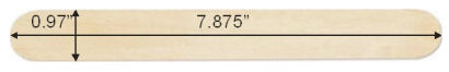
I
purchased a package of 45 large craft sticks from
Walmart. I drilled a 1/4-inch
hole in the end of 16 craft sticks and stacked them on top of the 1” platform.
I drilled a 1/4-inch hole in the baseboard, then secured the assembly to
the base with a 1/4-inch bolt and nut.
I now adjust the height of the platform by swinging out a number of
sticks. After the case is annealed,
I swing the entire platform out so the case can drop through a hole to an
aluminum pan. I swing the platform
back under the coil for the next case.
The 1” platform is just the right height to anneal .30-06 cases.
After winding the
coil, I used a 31/64” bit to drill through the brass rod I used to wind the
coil. This is just wide enough for a case
to fall through. I place the rod through
the coil so it sets on the platform, drop a case through the hole so it is
centered in the coil, then I remove the rod.
I do this during the last 10-seconds of the cool-down cycle.
My
Annealing Process
Here is the process I follow:
1.
Adjust
the craft stick platform for the appropriate height.
2.
Swing
the platform under the coil.
3.
Place
the hollow brass rod in the coil.
This helps to center the case.
4.
Drop a
case into the brass rod so it sets on the platform.
5.
Remove
the brass rod.
6.
Press
the Start button on the timer. This only has to be done once.
7.
After
the inductor shuts off, place the brass tube over the annealed case.
8.
Swing
out the platform so the case drops through the hole into a metal tray.
9.
Repeat
steps 2-5 and 7-8 for each case.
Once I
got into a rhythm I annealed 60 .30-06 cases fairly quickly.
It was actually a fun process!
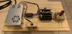
Summary
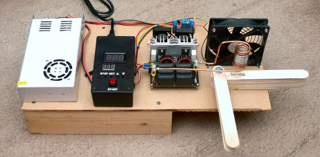
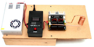
The
above photo shows my completed annealer.
So, what did this cost me? At
the time of this article this is what I paid:
|
Power Supply
|
$23.69
|
|
Timer
|
$12.02
|
|
Inductor Board
|
$32.69
|
|
2x 24v 40mm fans @ $2.69 each
|
$13.92
|
|
24v 120mm fan
|
$12.86
|
|
Fan Relay (4)
|
$7.50
|
|
Metric Screw Set
|
$18.87
|
|
Jumbo craft sticks (2 packs)
|
$7.94
|
|
Total
|
$129.49
|
If you
wanted to purchase the other parts I already had, you would need to purchase:
|
AC Power Socket
|
Ebay
|
$7.30
|
|
Case 546-1591XXDSBK
|
Mouser.com
|
$7.10
|
|
Momentary push button
612-PS1057A-RED
|
Mousr.com
|
$1,87
|
|
Terminal Connector Kit
|
Ebay
|
$8.99
|
|
Rubber Grommet Kit
|
Ebay
|
$8.99
|
|
Digital Volt Meter
|
Ebay
|
$6.89
|
|
16 AWG red/black wire, 5 ft
|
Ebay
|
$6.49
|
|
Line cord, 2 @ $4.12 +$3.50 shipping
|
Ebay
|
$15.24
|
|
Terminal Strip
|
Ebay
|
$6.99
|
|
1K 1/4W resistor (40)
|
Amazon
|
$3.99
|
|
Total
|
|
$73.85
|
This
was a fun and cost-effective project to build.
Using the inductive annealer I wouldn’t have to continually purchase
propane. You can build your own
annealer for under $200, and even less if you copy Tim’s annealer and you don’t
use a case or fans. I used the case
because I wanted to include a voltmeter and AC power socket.
Hopefully this will give me many years of service.
Addendum May, 2025
While annealing a batch of .223
Remington cases I discovered that the timer got hot and would shut down. I
could reset it by turning off the AC, waiting 10-seconds, then turning the AC
back on. I decided to add another 40mm 24-volt fan to the plastic case.
I cut a hole in the switch end of the case for the fan. I wired the
fan to the internal barrier strip, then mounted the fan with #6 hex-head screws
and nuts through pre-drilled mounting holes. Now, when the 24-volt power
supply comes on the fan blows air across the timer keeping it cool.
|