Building
a Dedicated 1911 .22LR Pistol
by Roy Seifert
Click here to purchase a
CD with this and all Kitchen Table Gunsmith Articles.
Disclaimer:
This article is for entertainment only and is not to
be used in lieu of a qualified gunsmith.
Please defer all firearms work to a qualified
gunsmith. Any loads
mentioned in this article are my loads for my guns and have
been carefully worked up using established guidelines and
special tools. The
author assumes no responsibility or liability for use of
these loads, or use or misuse of this article.
Please note that I am not a professional gunsmith,
just a shooting enthusiast and hobbyist, as well as a
tinkerer. This
article explains work that I performed to my guns without
the assistance of a qualified gunsmith.
Some procedures described in this article require
special tools and cannot/should not be performed without
them.
Warning:
Disassembling and tinkering with your firearm may
void the warranty. I
claim no responsibility for use or misuse of this article.
Again, this article is for entertainment purposes
only!
Tools
and firearms are the trademark/service mark or registered trademark
of their respective manufacturers.
Index
Introduction
Purchasing the Receiver
Purchasing Parts and Tools
Parts List
Tool List
Polishing the Frame
Frame Top
Dust Cover
Trigger Guard
Magazine Well
Fitting Beaver-Tail Grip Safety to Frame
Blending Frame and Grip Safety
Fitting the Mainspring Housing
Checking for Protrusions in the Magazine Well
Polishing Barrel
Bed and Feed Ramp
Performing
Additional Polishing
Installing the
Plunger Tube
Installing Fire
Control System
Preparing and
Installing Fire Control Parts
Fitting Thumb
Safety
Fitting Grip
Safety to Trigger
Adjusting
Trigger Pre/Over Travel
Polishing Fire
Control Parts
Performing
Function and Safety Checks
Cleaning Up and
Installing Small Parts
Bead Blasting
Bluing Parts
Lubricating and
Assembling All Parts
Test Firing
Custom Grips ___________________________________________________________________
Introduction
I
have a number of 1911’s in my collection; all of them I
built from scratch with hand-fitted parts.
Two of them are single-stack in .45 ACP, and one is a
double-stack, wide-body in 9mm.
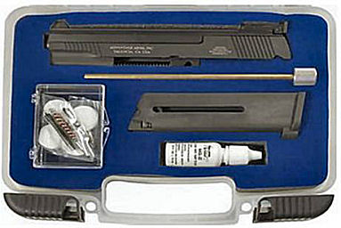
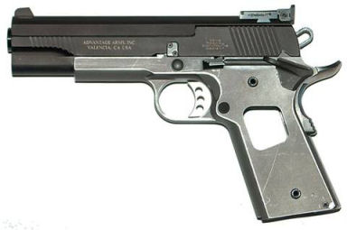
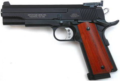
I also have an Advantage
Arms .22LR target conversion kit model 1911-22T that I
sometimes use on one of my 1911 .45 ACP frames.
The .22 conversion kit is an economical and fun means
to practice with a 1911, especially with the current cost and
lack of availability of .45 ACP ammo.
I chose this conversion kit because it was the target
model, and the slide locked back after the last round.
Some other conversion kits on the market do not offer
the slide lock feature. As
a plus the unit came with a cleaning kit and a nice carry
case. Rather than
having to swap the conversion kit onto a .45 frame, I decided
to build a dedicated 1911 .22.
Just in case you’re wondering, it is always more
expensive to build a gun from parts than to purchase a
complete gun, but where is the fun in purchasing when you can
build!
Purchasing
the Receiver
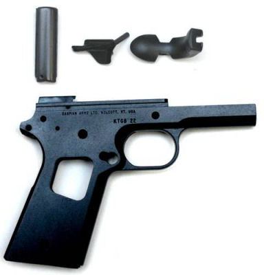
I
purchased a standard carbon-steel frame with a custom serial
number from Caspian Arms.
Caspian Arms offers many extras on their frames, such
as checkered front strap, integral plunger tube, integral
accessory rail, wide magazine well, and many others.
I did not order any extras except the custom serial
number. The custom
serial number I chose was KTGS 22 for “Kitchen Table Gun
Smith 22”. Because
the receiver was serialized I had to have it shipped to my FFL
dealer. Walt at
Caspian Arms indicated that they had about an 8-week backlog
of orders; which worked out fine for me because it gave me
time to purchase the additional parts to populate the
receiver.
True
to Walt’s estimate, the frame arrived at my FFL dealer two
months after ordering. After
filling out the paperwork and paying the transfer fee I
finally had the frame in my hands.
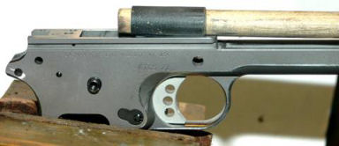
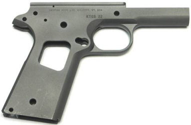
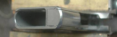
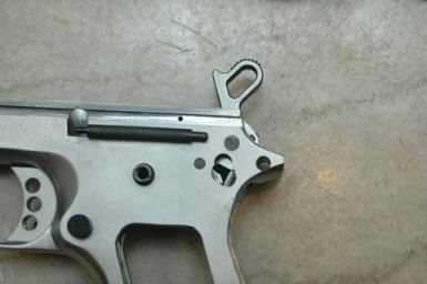
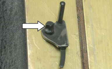
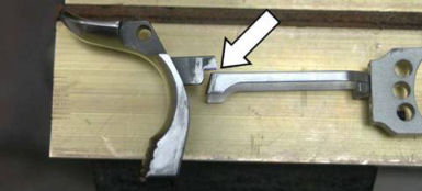
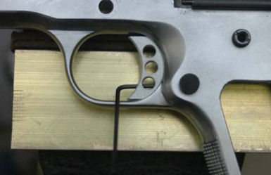
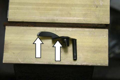
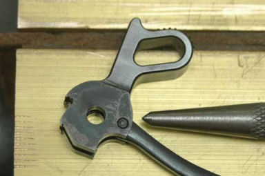
It is pretty much a standard GI 1911 frame, but ya
gotta love that custom serial number!
Notice the long, pointed “tails” on the rear of the
receiver where the standard GI grip safety fits.
These tails will be filed off and rounded to fit a
beaver-tail grip safety.
Purchasing
Parts and Tools
Below
is a list of parts and tools I purchased to build KTGS 22.
Most of the parts I found at Midway USA on sale.
Where possible I included the part number, but not the
price since prices change frequently.
This was my fourth 1911 build so I already had the
tools on hand, but they can be purchased from Midway USA or
from Brownells. Polishing
sticks I made from wooden dowels and 1/4“ flat wood stock
with 400 grit paper. I
wrapped the paper around the dowels, and glued the paper to
the flat stock.
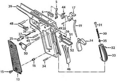
Parts
List
|
Drawing
Reference Number
|
Source
|
Part
No.
|
Description
|
|
4,
7, 18, 20, 31, 32, 34, 35, 45, 49, 51
|
www.midwayusa.com
|
572-340
|
Swenson
pin set
|
|
5
|
www.midwayusa.com
|
111-344
|
Smith
& Wesson disconnector
|
|
6
|
www.midwayusa.com
|
923-179
|
Ed
Brown Ejector
|
|
10,
27,30, 36, 41, 46
|
www.midwayusa.com
|
115-123
|
Wolff
.45 Government Spring Pack
|
|
13
|
Homemade
|
N/A
|
Grip
Panel
|
|
14
|
www.midwayusa.com
|
181-642
|
Ed
Brown speed bump beaver-tail grip safety
|
|
15
|
www.midwayusa.com
|
172-684
|
Slotted
Grip Screws (4)
|
|
16
|
www.midwayusa.com
|
734-065
|
Grip
screw bushing (4)
|
|
17
|
www.midwayusa.com
|
532-745
|
Smith
& Wesson hammer
|
|
19
|
www.midwayusa.com
|
659-211
|
Smith
& Wesson hammer strut
|
|
25
|
www.midwayusa.com
|
413-295
|
Nighthawk
extended checkered magazine catch
|
|
26
|
www.midwayusa.com
|
652-512
|
Wilson
Magazine Release Lock
|
|
30
|
www.midwayusa.com
|
237-409
|
Wilson
19lb mainspring
|
|
33
|
www.midwayusa.com
|
260-701
|
Kimber
flat checkered mainspring housing, polymer
|
|
37
|
www.midwayusa.com
|
358-241
|
Swenson
Plunger tube
|
|
44
|
www.midwayusa.com
|
125-678
|
Nowlin
sear
|
|
48
|
N/A
|
N/A
|
Slide
stop - Came with the conversion kit
|
|
50
|
www.midwayusa.com
|
215-306
|
Swenson
extended thumb safety
|
|
52
|
www.midwayusa.com
|
623-353
|
Nowlin
ultra-light trigger
|
As
you can see from the list, the result is a “Franken-pistol
mix-master” of parts. However,
everything was hand-fitted so they all fit and worked
harmoniously together.
Tool
List
Below
are the special tools I used to build KTGS 22.
Polishing
the Frame
A
gun should look as good as it shoots.
The more time and care I apply here will benefit in the
finished product. There
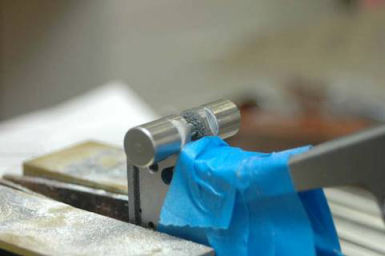
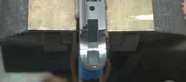
were several places I needed to address, but I started with
the top of the frame. I
put the frame in my vise with the top up and used the magazine
well filler to make sure I didn’t apply too much pressure.
The magazine well filler prevented me from crushing the
delicate frame. The
vise jaws were padded with leather so as not to mar the frame.
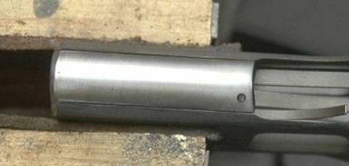
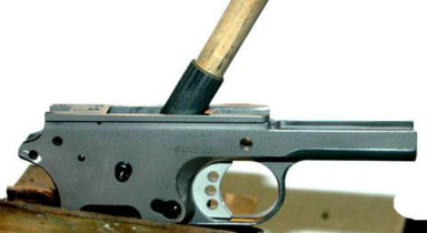
Frame
Top
The
top of the frame had some tool marks which I wanted to remove
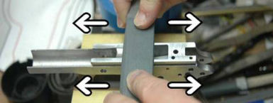
and polish. I
wrapped a piece of 400-grit paper around a bastard file and
polished the top until there were no more tool marks.
I needed to be careful to keep the file very flat as I
didn’t want to “bow” or round this top surface.
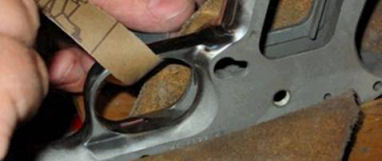
I used a “draw-filing” action where I laid the file
at right angles to the frame and moved the file parallel with
the frame (refer to the photo above).
After the tool marks were gone I finished polishing
with 600-grit paper.
Dust
Cover
A Dremel® tool is one of my favorite tools because of its
versatility, and it’s great for working on guns.
Because the Dremel® tool spins at up to 25,000 RPM or
more it can run away and cause some serious damage.
This tool has to be treated with respect.
When I have it turned on, it will do the work that I
desire, but if I don't pay close attention it could get away
from me. A
professional gunsmith once commented that the Dremel® tool
was his best friend because it generated a lot of business for
him!
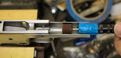
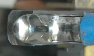
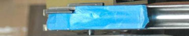
I
put a 1/2“ fine sanding drum on a Dremel® flex shaft.
I put 3 layers of blue tape around the chuck to prevent
scoring the dust cover while polishing.
I clamped the frame in the vise with the dust cover
level and facing me. I
turned the tool to speed setting #4, and while holding it in
both hands, smoothed the inside of the dust cover by moving
the tool back and forth until it was nice and shiny.
Too much pressure on the drum could cause gouges so I
just let the drum kiss the metal.
This
is plenty smooth for the inside of the dust cover, but I
wanted it really polished so I continued to polish with
400-grit paper wrapped around the sanding drum, then I
finished with 600-grit paper wrapped around the sanding drum
to perform the final polish.
Now
I needed to work on several more areas of the frame.
I’m using small tools and working gently.
I’ve already polished the inside of the dust cover so
now I needed to smooth out the upper edges and remove the
sharp corners.
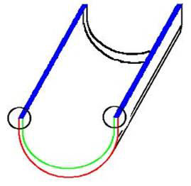
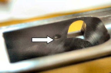
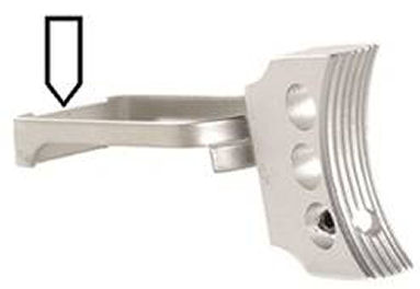
First
I took a jeweler’s file and carefully beveled the inside
edge of the end of the dust cover (green edge).
After beveling with the file I used my Dremel® tool
and a Cratex® tip to finish polishing this area.
I didn’t want to change any dimensions, just make it
smooth.
The
upper part of the dust cover should be flat and smooth (area
in blue). I used
400-grit paper wrapped around my bastard file to draw-file
these edges.
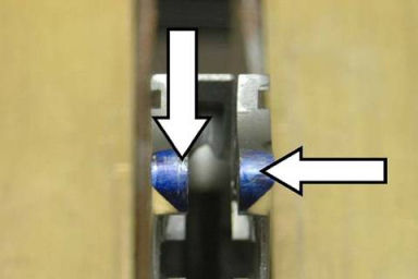
The
two sharp corners at the top end of the dust cover should be
relieved so they are no longer sharp (circled corners).
Again I used a jeweler’s file to round the corners,
then polished with a Cratex® tip.
As
part of the carry bevel I’m going to bevel the bottom front
edge of the dust cover (red edge).
The carry bevel prevents sharp edges from tearing up a
holster and my hand. I’ll
do more later, but for now I used a jeweler’s file and
Cratex® tip to smooth this edge as I did before.
Trigger
Guard
The
inside and outside edges of the trigger guard were also sharp.
I used a jeweler’s file and Cratex® tip to smooth
these edges as I did before.
The
under side of the frame inside of the trigger guard, and the
inside of the trigger guard itself had some deep tool marks
that I wanted to remove. I
took strips of 400-grit sand paper and polished these areas
using a back-and-forth “shoe shine” motion.
I replaced the paper strips frequently, and continued
polishing in this manner until the tool marks were removed.
Magazine
Well
The
magazine well has some sharp edges that I needed to address
with files and Cratex® bits.
I beveled and polished the outside edges of the
magazine well, and the inside edges ONLY where the magazine
fits. I did not
bevel and polish any of the inside edges where the mainspring
housing sits. I
also beveled and polished the outside and inside edges of the
round front strap.
Fitting
Beaver-Tail Grip Safety to Frame
This
has always been a fun process for me and when done right it
looks very clean and professional.
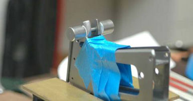
First I taped my frame along the back edge where the
grip safety goes to avoid nicking with the file.
Then I put the frame in my vise and installed the Ed
Brown grip safety jig.
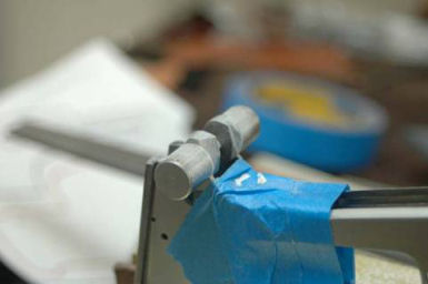
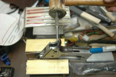
With
a bastard file I started taking the metal away from the two
“tails” of the frame making sure I removed the same amount
on each side. I
put chalk on the file to keep the teeth from getting full, and
moved the file in one direction only.
After about 20 strokes I used a brass brush to clean
the file and re-chalked.
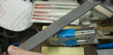
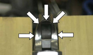
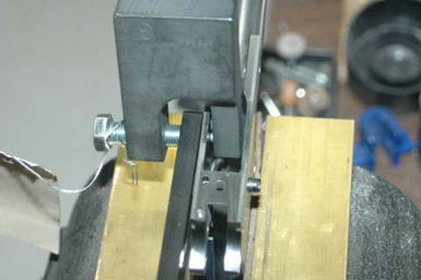
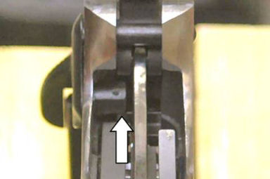
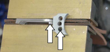
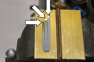
When
I got close to the hardened steel “rollers” on the jig I
switched to a Barrette file to remove more metal.
I took it right down to the rollers.
The rollers are made of hardened steel so the file
wouldn’t cut into them.
The above
photo shows the tails filed down to the jig.
Now
that I’ve cut the proper radius I needed to fit the grip
safety. I used a
blue marker to mark the radius on the frame that I just filed,
then installed the safety with a taper pin.
I used a soft-faced mallet to tap the taper pin in
fairly snug.
I
rotated the safety, then removed the taper pin and safety to
see any white marks that indicated I needed to remove a bit
more metal. I took
a jewelers file to gently remove a small amount of metal where
the white marks indicated.
I re-marked the radii and re-installed the safety with
the taper pin and continued to check for high spots until no
blue wore off.
Blending
Frame and Grip Safety
When performing the frame/grip safety blending I always wear a dust
mask and safety glasses because there’s quite a bit of metal
dust in the air which I don’t want to get into my nose,
lungs, or eyes.
I installed the grip safety onto the frame with a hammer pin, then
taped the grip safety down so the gun would be smooth when
being held.
Then I
took my Dremel® tool with a
1/4“ fine sanding drum and blended the frame with the bottom
of the grip safety until smooth.
I smoothed everything up by shoe shining with 400-grit
paper, followed with a Cratex® bit.
I
blended the top of the grip safety with the frame in the same
manner. The
objective here is to make a smooth surface for the web of the
thumb, and to make everything look smooth and professionally
fitted.
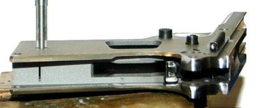
Fitting
the Mainspring Housing
Although
I purchased a polymer flat mainspring housing (MSH), I really
didn’t like the feel of the polymer.
I had a blue steel flat mainspring housing in my parts
bin which I decided to use.
I wanted the mainspring housing to fit just as cleanly
as I did the rest of the gun.
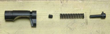
First I assembled the mainspring housing and parts as
illustrated above. I
installed the cap and plunger onto the mainspring, installed
them into the housing, put the housing in my vise and used a
punch to push the plunger into the housing so I could install
the retaining pin. I
wore safety glasses in case the punch slipped.
There is nothing worse than having springs and
small parts fly off to who knows where and trying to find them
in a crowded gun room. I
think they go to the same place as odd socks!
I assembled the sear spring and mainspring housing in the frame.
I put 3 layers of tape over the bottom of the magazine
well, and then took my bastard file and draw-filed the bottom of the MSH
until it was flat with the frame.
I then polished the bottom of the frame and MSH with a
400-grit paper wrapped around a bastard file.
The rear corners of the frame were beveled but didn’t match the
MSH. I put a fine
sanding drum on the Dremel® and beveled the corners of the
frame to match the MSH, then polished out the tool marks with
a Cratex® bit.
I had used this flat mainspring housing to practice checkering, but
buggered it up. I
used my bastard file to draw-file off the checkering, then
shoe-shined it with 400-grit paper.
Since a .22 LR doesn’t recoil very much I don’t
really need any checkering to keep the gun in my hand.
Checking
for Protrusions in the Magazine Well
Sometimes new grip screw bushings protrude into the magazine well
so I wanted to make sure they set flush and wouldn’t drag on
the magazine. First
I removed the main spring housing and sear spring.
I discovered that the grip screw bushings did not screw easily into
the frame. I
chased the threads with a .236” – 60 grip screw bushing
tap to make sure the threads were clean, then I installed the
grip screw bushings in the frame, being careful not to
cross-thread them, and made them fairly tight.
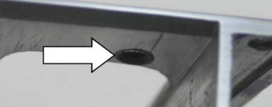
Using my bastard file I smoothed the inside sides of the magazine
well where the bushings might be slightly sticking up.
On this particular frame the bushings protruded on only
one side. I left
the bushings installed for the rest of my work.
Since some of the bushings were now of different
lengths I needed to make sure they went back in the same
locations when I removed them in preparation for final
finishing. After I
removed each bushing I put a piece of tape around it and
labeled its location so I would know where to put them when I
re-assembled the gun.
I re-installed the sear spring and mainspring housing and checked
to see if the sear spring tab was protruding through the slot
into the magazine well. Mine
wasn’t, but if it was I would have used a #0 pillar file to
smooth the tab flush.
Polishing
Barrel Bed and Feed Ramp
I now wanted to make the barrel bed ready to accept a
barrel. This
process isn’t necessary for my .22 top end, but I wanted
this frame to be able to accept a .45 top end as well.
Performing
Additional Polishing
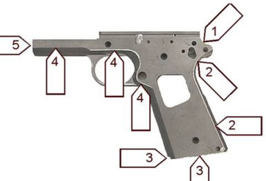
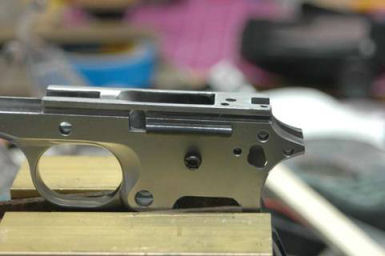
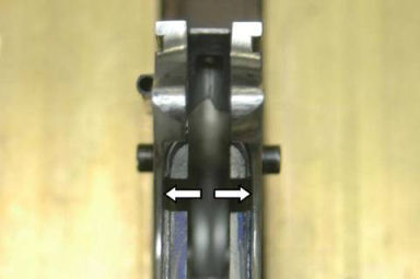
Now
I did some additional work on the frame.
Sharp edges I beveled with a jewelers file and polished
with a Cratex® tip. Wherever
I had a frame line, not an edge, I used just a Cratex® tip to
make that line a bit softer, but did not eliminate it.
Refer to the above photograph for references to the
numbered areas described below.
1.
First
I beveled the sharp outside edge at the rear of the frame
between the slide and the grip safety with a file then Cratex®
bits. This edge
was left very sharp after I blended the grip safety with the
frame.
2.
Next
I worked on the edges of the rear of the frame where the grip
safety and mainspring housing set.
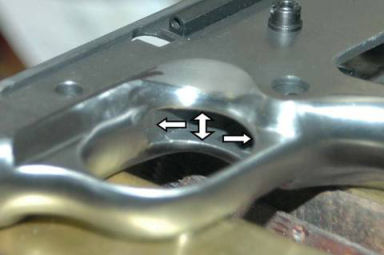
3.
I
then beveled the outside of the magazine well including the
front round edge.
4.
I
slightly softened all frame lines with a Cratex® bit, but I
was careful not to do too much.
5.
Finally
I beveled the outside edge of the dust cover.
I did this previously but I just wanted to make sure I
got the sides as well.
I
took a careful look at the frame just to see if there were any
other areas that needed work.
I decided to run a Cratex® bit over the top edge of
the grip safety because that edge felt a bit sharp.
Installing
the Plunger Tube
The
plunger tube is probably the most fragile part of the 1911.
I’ve had to install three plunger tubes on another
gun I built because of my own stupidity.
But, this is how we learn.
Before I could install the plunger tube I needed to
chamfer the holes where the tube attaches to the frame.
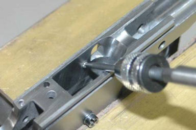
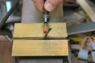
I
chucked a 1/8” carbide ball cutter into a keyless chuck,
which I then inserted into my gunsmith screwdriver.
I put the ball end against the hole on the inside of
the frame and rested the shank on a piece of leather and
turned it until I had a nice chamfer.
This chamfer will help hold the plunger tube tightly
against the frame. The
leather is not shown in the above photo for clarity.
The leather prevented me from marring the frame.
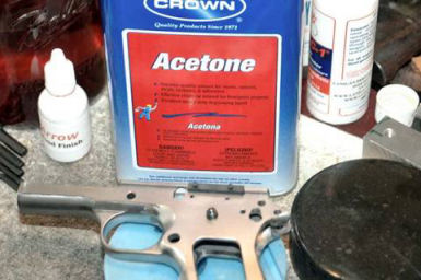
I
cleaned off all the shavings, then cleaned the area with
Acetone using a Q-Tip. I
also cleaned the back of the plunger tube with Acetone.
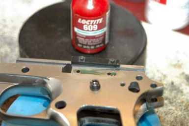
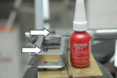
Now
that everything was clean I put a thin bead of green Loctite
609 in the area where the plunger tube will be and made sure I
got some in the holes. I
also put some on the back of the plunger tube itself.
I
inserted the tube into the holes and made sure the small hole
was to the front, and the large hole was to the rear.
I cleaned away the excess Loctite with a Q-tip and
acetone, then put the frame in my vise.
I applied just enough pressure to keep the plunger tube
in place. I let it
set for 24 hours to give time for the Loctite to set up.
After
the Loctite had time to set up, I expanded the stud/rivets
with a plunger tube staking tool.
In
the process of cutting the chamfer with the ball end I raised
a burr around the two holes.
I took my 400-grit polishing stick and polished off the
burr so again, the inside of the magazine well was nice and
smooth for the magazine.
Installing
Fire Control System
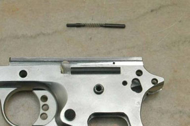
Now
I was ready to install the fire control system.
The first part to go in was the trigger, but first I
had to prepare the frame.
The area in which the trigger rides needed to be
smoothed. First I
polished the two trigger stirrup channels, one on each side of
the frame. I used
narrow 400-grit polishing stones until both channels were nice
and smooth.
Then
I polished the four areas up forward where the trigger sticks
out of the frame. Again,
I used my polishing sticks to smooth the top, bottom, and
sides of the trigger cut.
I needed to be careful not to change any dimensions,
only smooth. There
were some burrs here that prevented me from installing the
trigger, but smoothing these surfaces removed the burrs and
the trigger fit perfectly.
Now
that the trigger channel was all smoothed I polished the sides
of the trigger stirrup with a Cratex® bit.
Now I tried the trigger in the frame.
Because it fit perfectly I didn’t have to perform any
additional fitting. If
the trigger had been oversized I would have carefully polished
the top and bottom of the trigger shoe with 400-grit paper
until it just fit.
Next
I assembled the magazine catch with the magazine catch itself,
the magazine catch spring and the magazine catch lock.
After I inserted the spring and lock into the catch I
rotated the lock counter-clockwise until the tab caught in the
slot.
I
inserted the assembly into the frame with my finger holding it
in. I held a
screwdriver in my other hand and rotated the lock until it set
in the groove in the frame.
I worked the magazine catch a few times to feel for any
resistance.
At
this point I carefully inserted an empty magazine to see if it
contacted the trigger stirrup.
The magazine slid in smoothly with no contact.
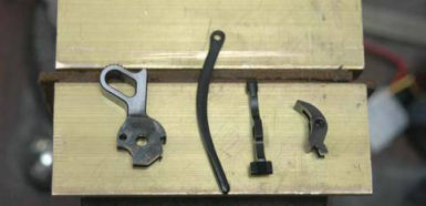
Preparing
and Installing Fire Control Parts
Now
that the trigger and magazine catch were installed I continued
installing the fire control system.
The parts I needed were:
- The
Sear
- The
Disconnector
- The
Hammer
- The
Hammer Strut
- The
Hammer Strut Pin
- The
Plunger Tube Assembly
- The
Hammer Pin
- The
Sear Pin
First
I smoothed the sides of the hammer and sear by rubbing them on
a flat sheet of 600-grit paper.
Then I rubbed the corners of the sear on a 400-grit
polishing stone to break the corners.
Next
I smoothed all sides of the hammer strut.
First I used a fine polishing stone on my Dremel® tool
set at a slow speed just to remove the high spots and sharp
edges. Then I
finished with a Cratex® bit.
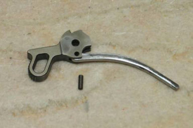
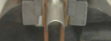
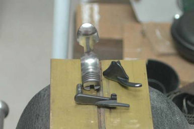
I
laid the hammer on a hard flat surface, lined up the hole in
the hammer with the hole in the strut and tapped the pin in as
pictured above. I
was careful to start the pin straight and get it in all the
way. Once this was
assembled, I stoned both areas where the pin comes through to
make sure that it was smooth.
Now
I assembled the plunger tube parts.
The small pin went to the front; the larger pin went to
the rear. Then I
installed the assembly into the plunger tube.
I
took the disconnector and tried to put it in the hole from the
top. Mine fit
perfectly, but if it hadn’t I would have polished the ring
at the top of the disconnector until it would go through the
hole
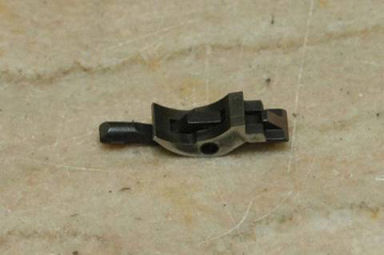
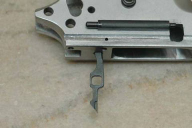
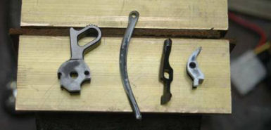
I
assembled the 'cradle' with the sear and disconnector as shown
in the photo above. I
installed the sear and disconnector into the frame and
installed the sear pin to keep them in place.
I
now installed the hammer with the hammer pin.
Fitting
Thumb Safety
Now
I fit the thumb safety. I’ve
done this on other guns and have had problems with the
thickness of the frame where the safety wouldn’t completely
rotate. I removed
all parts from the frame except for the trigger and magazine
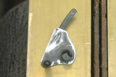
release. First I
made sure the back of the safety was perfectly flat with no
raised casting marks. I
filed away any raised edges with a jeweler’s file.
Note in the photo above how I had to polish off the
raised edge around the outside of the safety.
Then
I installed the thumb safety so that it was flat against the
frame. I moved the
safety up and down to see if it would rotate freely in the
safety cutout slot in the frame.
My safety rotated freely and did not bind on the frame.

Now
that the safety rotated freely, I removed it and re-installed
the sear, disconnector, and sear pin.
Next I installed the sear spring making sure that the
little tab at the bottom of the spring was in the slot in the
frame, and the flat at the top of the left most leaf was
against the bottom of the sear.
I installed the mainspring housing and pinned it in
place with the mainspring housing pin,
then I installed the hammer and hammer pin.
I
cocked the hammer and tried to install the safety.
It wouldn’t go all the way in because it was hitting
against the sear. I
lightly filed the engagement surface with a file only 2 or 3
strokes at a time until the safety would go in and I could
engage it, making sure it blocked the sear.
Fitting
Grip Safety to Trigger
Now
I was ready to fit the beavertail safety to the trigger
stirrup. First I
removed all of the trigger parts except the trigger and the
magazine catch. In
this way I could see how the grip safety engaged the trigger
stirrup. In the
safe position the grip safety prevents the trigger from moving
rearward to disengage the sear.
When I grip the gun the grip safety is depressed and
rotated and the leg on the safety is moved up and out of the
way of the trigger stirrup.
I installed the beavertail safety and the thumb safety
and kept the thumb safety in the lowered or fire position.
I
then installed the mainspring housing and held it in with the
retaining pin half-way in.
By looking inside the frame I could see how the grip
safety contacted the trigger stirrup.
I
removed metal from the bottom of the grip safety leg with a
file until the trigger would slide under it when the grip
safety was depressed. I
then polished the top of the rear of the trigger, and the
surface I just filed with a 400-grit polishing stone to make
them smooth.
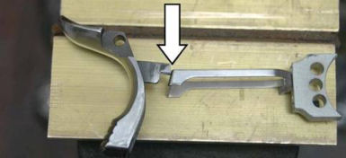
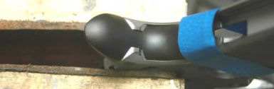
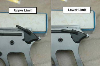
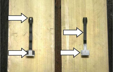
Grip
safety out, trigger blocked
Grip safety in, trigger not blocked
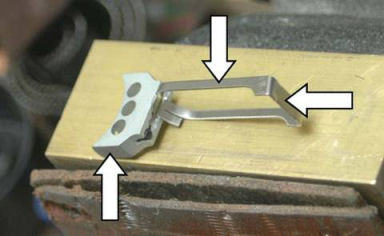
Adjusting
Trigger Pre/Over Travel
I
purchased a trigger with pre-travel adjustment tabs and an
over travel set screw, so now I adjusted pre-travel and over
travel. First I
installed the complete trigger group.
Then I pulled the hammer back and let it rest in the
half cock position.
The
first time I performed the pre-travel adjustment on another
pistol I gripped the trigger shoe to bend out the adjustment
tabs. This caused
the trigger shoe and stirrup to become so misaligned I spent
over one hour getting them realigned.
So now I only grip the stirrup and tab, never the
trigger shoe.
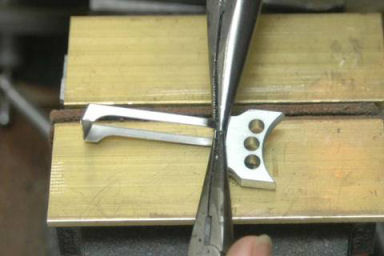
With
the hammer in the half-cock position the trigger should have
no rearward travel at all.
I used two pair of needle-nose pliers to bend the tabs
out by gripping only the stirrup and tab.
I
really didn’t have to bend the tabs very far to take up the
pre-travel. I’ve
done this before and the amount of bend is about the same for
most guns.
Now
for the over-travel adjustment.
I cocked the hammer and turned the adjustment screw in
until the hammer didn’t fall.
Then I backed out the screw 1/2 turn to see how it
worked. I held the
hammer back when I pulled the trigger and gently let the
hammer go forward. I
could feel the half-cock notch on the hammer just touch the
sear so I backed out the adjustment screw another 1/4 turn.
I tested it again just to make sure the half-cock notch
didn’t touch the sear. Once
set I used some Loctite blue to lock the set screw in place.
Polishing
Fire Control Parts
Now
I performed some final polishing on parts of the trigger group
to get a good, reliable trigger pull.
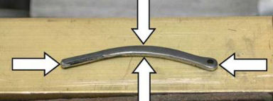
First I polished the front of the two left leaves of
the sear spring. The
left-most leaf contacts the sear and allows the sear to return
to the fire position. The
middle leaf contacts the slanted surface of the disconnector
and allows it to return to the fire position.
The right leaf returns the grip safety to the safe
position. I also
needed to make sure that the two outside leaves did not
contact or drag against the frame.
I polished the leaves by rubbing the appropriate
surface against my 400-grit polishing stick.
Next
I cleaned up and polished the disconnector.
I polished the slanted area by rubbing it on a 600-grit
polishing stick. I
also polished the flat portion behind this.
Finally I used a Cratex® tip to polish the tip of the
extractor to make it very smooth for the disconnector rail on
the slide to ride over. I
also polished the flat back of the stem.
Now
on to the sear. With
my Dremel® and a Cratex® tip I polished the two lower legs
of the sear. With
the curve facing me I polished the fronts and ends.
I
had already polished the inside of the thumb safety when I
fitted it, but I polished the sharp edge on the lower part of
the lever.
Performing
Function and Safety Checks
Now
it was time to see if all my hard work had been worth it.
I completely assembled the gun and used some dummy
rounds to perform the function and safety checks.
First I locked the slide in the rear position with the
slide stop. I
loaded ONE round into an empty magazine and inserted it into
the gun. I
released the slide stop and allowed the slide to go forward
into battery. It
fed the round into the chamber smoothly.
Then I pulled the slide back smartly and the round
ejected briskly. Good
work!
Now
with the gun empty and no magazine in it I again locked the
slide back with the slide stop.
I held the trigger fully to the rear and released the
slide and let it go into battery.
The hammer stayed back in the full cock position.
I repeated this a second time without holding the
trigger back, and again the hammer stayed at full cock.
This is the only time I will allow the slide to slam
forward without a loaded magazine.
With
the gun empty and no magazine I racked the slide to put the
hammer in the full cock position.
With my hand off of the grip safety I pulled the
trigger; it did not drop the hammer.
With
the gun empty and no magazine I racked the slide to put the
hammer in the full cock position.
Gripping the gun normally, I engaged the thumb safety
and pulled the trigger. Again,
the hammer did not drop, which is correct.
With my finger off the trigger I moved the thumb safety
to the fire position; the hammer did not drop.
I
did a little work to make the trigger pull smoother by
“pushing” the hammer.
I disassembled the gun and removed the grip safety.
I then reassembled the gun and cocked the hammer.
With my left thumb I applied additional forward
pressure to the hammer, then pulled the trigger to allow the
hammer to fall. I
did this 5 or 6 times which helped the hammer and sear mating
surfaces to work in quicker.
I
tested to see if the disconnector was resetting properly by
first pulling the hammer back into the full cock position.
I then pulled the slide back just until it pushed on
the disconnector. With
my left hand pushing on the slide I pulled the trigger, then
released the slide keeping the trigger pulled.
When I released the trigger I should have heard a click
as the disconnector reset, but the trigger would not return to
the forward position.
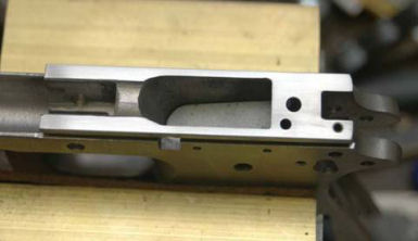
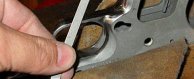
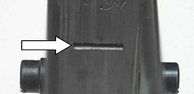
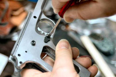
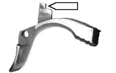
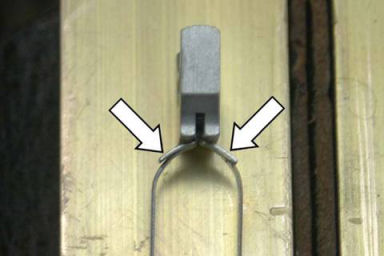
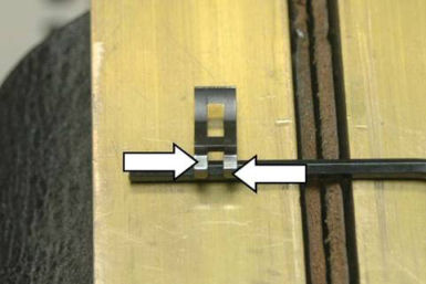
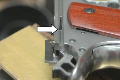
Upon
close examination I discovered that the top of the rear part
of the trigger bow was dragging on the bottom of the
disconnector. I
carefully filed the top of the rear of the trigger bow as
shown in the above photo until the trigger and disconnector
reset as they should.
Cleaning
Up and Installing Small Parts
Now
I needed to check my work and make sure I have done all of the
things that have to be done to build a Custom 1911 pistol.
I installed a .45 ACP ejector I had in my parts bin
onto the frame. Although
this ejector is not used for .22 LR cartridges, I didn’t
want there to be an empty space below the slide where the
ejector should go. Besides,
I someday may want to put a .45 upper on this frame.
First I pinned the ejector in and made sure that the
pin was flush on both sides.
It went in from right to left.
Some
of the internal parts I polished I wanted to protect the bare
metal so I cold-blued them instead.
I used a cotton swab dipped in acetone to degrease
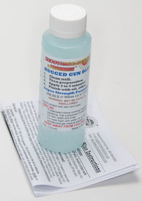
them, then I suspended them in .
Shooter
Solutions™ Rugged Gun Blue until I got a nice deep blue.
After removing the part I wiped it dry, then stopped
the bluing process by wiping with gun oil.
I only blued the bottom half of the hammer because I
like the bare steel look, but I didn’t get the deep blue I
wanted I think because this part is hardened.
Next
I staked in the hammer strut pin to make that sure it stays
put. I used a
pointed punch to make a dent in the center of each end of the
pin to make sure that the pin wouldn’t come out.
Next
I removed the grip screw bushings and reinstalled them with
Loctite red to insure they would not come out when I removed
the grip screws. It
is very irritating to have the bushing come out with the
screw.
Bead
Blasting
Now
that I have a fully functioning 1911 it’s time to enter the
home stretch. First
I needed to prepare all the parts I planned to blue.
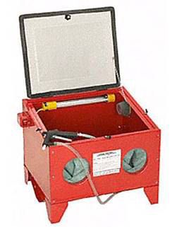
I purchased a used blast cabinet for about half the
price of a new one and glass bead blast media from ebay.
I wanted all visible parts to be blued so they would
first have to be bead blasted to get the same texture and
remove any original bluing.
Some
of the polished/fitted areas I didn’t want to have damaged
by the bead blasting so I protected them with masking tape.
I taped the feed ramp, top, and slide rails on the
frame.
I
took the parts to my blast cabinet and worked with the frame
first. I had my
air compressor set to 100 PSI, the maximum for the cabinet,
and held the gun fairly close to the work piece.
I made a slow back and forth pass over all external
areas until I got a nice even matt texture.
I made sure there was no bluing left on the ejector,
grip screw bushings, firing pin stop, plunger tube, and front
and rear sights. There
were a couple of areas Dremel® tool with a Cratex® bit got
away from me, but the bead blasting eliminated the marks.
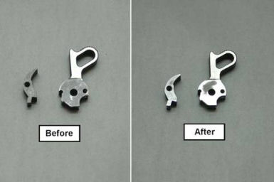
Before Bead Blasting - Shiny or Blue
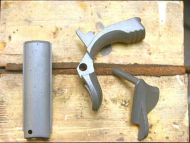
After Bead Blasting - Matt Texture, No Blue
Then
I concentrated on the smaller parts.
Again I made sure there was no bluing left on any of
the previously blued parts.
Bluing
Parts
Since
my .22 LR conversion kit was blued I decided to try my hand at
bluing the frame so it matched.
Professional, commercial bluing requires hot dipping
tanks and special bluing salts.
Shooter
Solutions™ has a cold bluing solution that comes out almost
looking as good as, and durable as commercial bluing.
I purchased two 4-ounce bottles of their 2.5X
Concentrated Rugged Gun Blue just to see how it would come
out.
Preparation
is everything. First
I had to clean and degrease all the parts I planned to blue.
I wore vinyl gloves so I wouldn’t contaminate the
parts with oil from my skin.
I used acetone to clean and degrease all of the parts.
I
poured one bottle of solution into a 1-cup glass measuring
cup. I used a bent
paper clip to suspend each of the small parts in the gun blue
solution for one minute. I
removed the part from the solution, dried it off, then coated
it with gun oil.
I
poured both bottles of bluing solution into a plastic pan that
came from my favorite Chinese restaurant.
I save these plastic tubs and pans and use them for
keeping small parts together, cleaning parts, etc.
After I degreased the frame I laid it in the solution.
The solution only covered half of the frame so I had to
keep flipping the frame to ensure it was evenly blued.
After about 45-seconds on each side I removed the
frame, dried it off, then coated it with gun oil.
Overall
I was very pleased with the results as you can see from the
above photo. We’ll
see just how durable this finish really is with time and use.
Lubricating
and Assembling All Parts
First
I degreased all parts by spraying with brake parts cleaner,
then dried with an air compressor.
I lightly coated all parts with BreakFree CLP then
wiped them clean.
I
reassembled the gun and put some good gun oil on the internal
moving parts. Personally
I think the result is much better than I had hoped.
Test
Firing
Now
I checked all of the functions of my 1911.
First I inserted the .22LR magazine and made sure it dropped out smoothly. I
re-checked the thumb safety for solid operation and saw that
it clicked in place firmly.
I also re-checked the grip safety function making sure
that it released the trigger when it should and that it did
not hold the trigger back when I pulled the trigger for the
next shot.
The
test fire procedure is very important.
I started with a single round in a magazine and with
the slide locked back, loaded that one round into the chamber
by depressing the slide stop and letting the slide slam home.
The round chambered with no hang-up.
I fired that one round and made sure the slide locked
back. With it
locked back, I inserted a magazine loaded with two rounds,
chambered the first round, and fired both shots.
I did not have any “doubling” where both shots were
fired with only one trigger pull.
This would have been a dangerous condition that I would
have had to fix before loading and shooting a full magazine.
Since
all seemed to be well I shot about 100 rounds to make sure
that everything was working correctly.
This also helped to “break in” the gun.
Man this gun was tight and shot better than I did!
I didn’t have any failures-to-feed (FTFs) or
failures-to-eject (FTEs) and the gun put the shots right where
I was aiming after adjusting the rear sight!
Reliability and accuracy; the results of a job well
done.
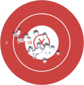
So
how does it shoot? My neighbor said it was really
smooth. The above target is 30 rounds at 8 yards so it
is not only smooth, but accurate as well. The trigger
breaks at a crisp 3 1/2 pounds which makes this gun a pleasure
to shoot.
Custom
Grips
Now that everything was working correctly I wanted to make a
set of custom grips. I have done this before (refer to
my article Making Custom Handgun
Grips) and they come out beautifully. Rather
than use wood I decide to use black Delrin® which is a
polyoxymethylene (POM), also know as acetal, polyacetal, and
polyformaldehyde. It is a synthetic polymer
thermoplastic used in precision parts requiring high
stiffness, low friction, and excellent dimensional
stability. Delrin® is DuPont's name for this polymer,
and I have found that it machines like metal and sands like
wood.
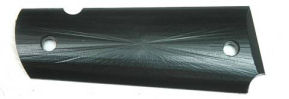
I
performed the drilling, milling, and shaping processes as
described in my article. You can see in the above photo
that the final shaping process left tool marks
behind.
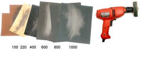
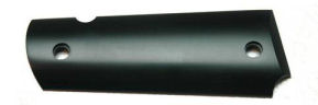
After
completing the shaping on my hobby CNC mill I sanded off the
tooling marks and polished with progressively finer grits of
sand paper starting with 150-grit and progressing to 220, 400,
600, 800, and 1,000-grit paper. I used a buffing wheel
on a drill with polishing compound to get the final high-gloss
finish I was looking for.

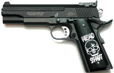
I
created a design that I engraved into the grips using my CNC
mill and a 0.015" bit. I tweaked the design just a
bit and put the spider web hole in the center of the O in
SHOT.
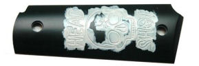
After
I completed the engraving I filled the lines with white epoxy
appliance touch-up paint. I painted the entire design so
the lines were filled with paint, then allowed the paint to
thoroughly dry. I used a cotton cleaning patch and
odorless mineral spirits to remove the excess paint from the
surface so just the filled lines were left behind.

As
you can see from the above photo the white lines really stand
out from the black polymer grips. So now I am fully
prepared for the zombie apocalypse!
|