Building
the V-10 Hog Hammer
by Roy Seifert
Click here to purchase a
CD with this and all Kitchen Table Gunsmith Articles.
Disclaimer:
This article is for entertainment only and is not to
be used in lieu of a qualified gunsmith.
Please defer all firearms work to a qualified
gunsmith. Any loads
mentioned in this article are my loads for my guns and have
been carefully worked up using established guidelines and
special tools. The
author assumes no responsibility or liability for use of
these loads, or use or misuse of this article.
Please note that I am not a professional gunsmith,
just a shooting enthusiast and hobbyist, as well as a
tinkerer. This
article explains work that I performed to my guns without
the assistance of a qualified gunsmith.
Some procedures described in this article require
special tools and cannot/should not be performed without
them.
Warning:
Disassembling and tinkering with your firearm may
void the warranty. I
claim no responsibility for use or misuse of this article.
Again, this article is for entertainment purposes
only!
Tools
and firearms are the trademark/service mark or registered trademark
of their respective manufacturers.
Background
I am an avid gun collector and shooter, but have never been
a hunter. As I
get older I find I would like to experience “the thrill of
the hunt.” I’ve
tried my hand at turkey hunting, and when paired with a
knowledgeable and experienced hunter, I had a great time and
thoroughly enjoyed the experience.
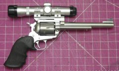
I decided I would like to try my hand at hog (wild
pig) hunting, specifically with a handgun, so I decided to
build my idea of the ultimate hog hunting handgun, the
“V-10 Hog Hammer.”
I decided
to use a stainless steel Ruger Blackhawk in .45 LC with a 7
1/2“ barrel as the platform for my project.
The reasons for this were numerous.
A long time shooting friend purchased a Ruger Bisley
Blackhawk in .45 LC with a 7 1/2“ barrel to use for
hunting. After
reading an article about how to safely load the .45 LC up to
.44 Magnum performance and beyond I agreed with his
decision. Ruger
makes the Bisley Blackhawk only in a blued version, but I
wanted stainless steel so I had to get the regular
“plowshare” grip Blackhawk.
Caution:
The following load is above SAAMI specifications and
should be approached with caution and used only in modern
firearms. The
author of the article I read had a pet hog load of 20 grains
of Alliant 2400 under a 300 grain hard cast lead wide flat
nose bullet. I
purchased a Lee 300 grain .452 wide flat nose gas check bullet
mold and cast my own. This
load chronographed from my Marlin 1894 Cowboy at 1500 feet per
second (fps), and from the 7 1/2” Blackhawk at 1240 fps.
Pressure was measured at 32,000 PSI using a Pressure
Trace™ unit. Although
this is beyond some published maximums for this caliber, many
powder and bullet companies are publishing loads within this
range specifically for use in modern firearms.
Planned
Improvements
Ruger makes a fine single-action revolver.
But like most production firearm manufacturers they
can’t afford to take the time to make the custom
improvements to really make this revolver into an excellent
shooter. Based on
Internet research, apparently Ruger revolvers have other
problems that are counter-productive to accuracy, which I will
identify later. Beginning
with the stainless steel Ruger Blackhawk 7 1/2“ barrel in
.45 LC I planned to make the following improvements:
- Install
a Wolff spring kit. I
really like how this smoothes and lightens the action.
- Lighten
the trigger pull – at the same time eliminate some of
the creep inherent in all Ruger single-action (SA)
triggers.
- Install
a wide spur hammer ala Super Blackhawk.
I don’t want my thumb to slip off the hammer
under the stress of “buck fever” (or should I say
“hog” fever) or in cold or wet conditions.
- Checker
the hammer spur for greater purchase.
- Install
a Hogue single piece rubber grip.
These hog loads can kick quite a bit and the
plow-share grip will rotate in my hand under recoil.
I want to control the recoil better.
- Install
a scope mount for a red dot sight or 2x pistol scope.
I want to be able to interchange the optics
depending on the shooting conditions; red dot for close
range, 2x scope for long range.
- Port
the barrel – I plan to drill 5 holes along either side
of the front sight base to help reduce recoil.
- Open
up the chamber throats if necessary.
- Lap
the barrel – This will improve overall accuracy.
- Convert
existing pawl into a free-spin pawl.
This makes single reloads very easy.
I had
thought about reducing the barrel to 6” for easy carrying,
but decided I wanted the extra length especially because I’m
going to port it.
Install
Spring Kit and Wide Spur Hammer
First I installed the spring kit.
I purchased kit RSA-106 from Brownells
which contained a reduced power trigger return spring, 17, 18,
and 19 lb. hammer springs (factory is 23 lb.), and a stronger
base pin plunger spring. First
I completely disassembled the gun and polished all trigger
parts and pins. I
made sure the trigger was not rubbing against the grip frame.
(One of my Vaqueros wouldn’t work with the reduced
power trigger return spring because the trigger was rubbing
against the grip frame. I
had to relieve that edge of the trigger slot for the gun to
function with the Wolff spring.)
After
polishing, cleaning and oiling all internal parts I
reassembled the gun using the spring kit with the 17lb.
mainspring to test for reliable function.
I purchased a wide-spur hammer from Brownells and
replaced the factory hammer at the time I reassembled the gun.
The gun functioned well and all springs worked as they
should, but I encountered my first problem.
If I cocked the hammer and pulled the trigger back at
the same time something in the lock work hung up which caused
a very heavy trigger pull.
By holding the hammer back and pulling the trigger 2-3
times I could feel something flexing, then I heard a
“click” inside the action and the heavy trigger tension
was gone.
Over the
years I’ve worked on dozens of Ruger single action revolvers
and every one was just a bit different due to manufacturing
variances. This
was one of those instances where, due to the manufacturing
process, something was causing the lock work to hang up.
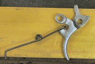
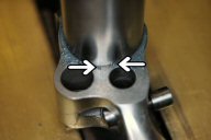
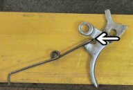 I
discovered that the end of the trigger return spring was
catching on the rear edge of the transfer bar arm as you can
see in the left photo. There
was a small ridge left from the casting that would catch the
end of the spring. Eventually,
the spring would rotate away from the arm causing the audible
“click”, which relieved the spring tension.
I checked my other spring kit (I always keep a couple
in the shop) and also compared it to a factory spring.
They were all the same dimension; therefore something
had to be done about the trigger. I
discovered that the end of the trigger return spring was
catching on the rear edge of the transfer bar arm as you can
see in the left photo. There
was a small ridge left from the casting that would catch the
end of the spring. Eventually,
the spring would rotate away from the arm causing the audible
“click”, which relieved the spring tension.
I checked my other spring kit (I always keep a couple
in the shop) and also compared it to a factory spring.
They were all the same dimension; therefore something
had to be done about the trigger.
 My
solution was to relieve the inside edge of the transfer bar
arm so the end of the spring wouldn’t catch.
I used my milling machine and a 1/8” end mill to make
the relieving cuts, then smoothed it with the edge of a cutoff
wheel and my Dremel tool.
I could have simply used my Dremel tool to relieve that
edge, but I think it would have taken longer.
There is no weight or tension on the transfer bar, but
like most things Ruger builds, this arm was probably
over-engineered. My
relief cut should have no adverse effect on function,
durability or reliability. My
solution was to relieve the inside edge of the transfer bar
arm so the end of the spring wouldn’t catch.
I used my milling machine and a 1/8” end mill to make
the relieving cuts, then smoothed it with the edge of a cutoff
wheel and my Dremel tool.
I could have simply used my Dremel tool to relieve that
edge, but I think it would have taken longer.
There is no weight or tension on the transfer bar, but
like most things Ruger builds, this arm was probably
over-engineered. My
relief cut should have no adverse effect on function,
durability or reliability.
Lighten
the Trigger Pull
There are some tricks I use to make a Ruger SA trigger lighter
and crisper. First
and foremost is installing the spring kit as performed above.
With most Ruger SA triggers the trigger sear sits too
deeply on the hammer notch.
Also the engagement surfaces are usually just rough
ground as they come from the factory.
This makes a very safe, but long and creepy trigger
pull. Some of the
things I can do are to reduce the hammer notch to about
0.014”, cut a break-away angle on the rear of the trigger
sear, and bevel the edges of the trigger sear so less surface
area engages the hammer. These
processes require special tools and jigs in order to keep the
surfaces square.
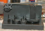
I installed
the hammer in my Power Custom Series 2 stoning fixture using
the universal adapter. I
used the original hammer pivot pin inserted groove first into
one of the holes in the adapter.
The pin was held in place by a set screw.
I made sure the set screw contacted the groove so as
not to raise a burr on the outside of the pin.
I marked the front edge of the hammer notch with a blue
marker and adjusted the fixture until my stone was flat across
the front of the notch. The
notch in my hammer measured 0.022” so I took a 220 grit
stone and carefully reduced the depth of the notch to
0.014”.
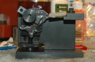 I
then rotated the hammer so I could polish the engagement
surface of the hammer notch as shown in the left photo.
I marked the surface with a blue marker and made sure
to adjust the fixture so I was polishing this surface
perfectly flat. I
used my hard Arkansas stone with a beveled edge to
final-polish the surface. I
then rotated the hammer so I could polish the engagement
surface of the hammer notch as shown in the left photo.
I marked the surface with a blue marker and made sure
to adjust the fixture so I was polishing this surface
perfectly flat. I
used my hard Arkansas stone with a beveled edge to
final-polish the surface.
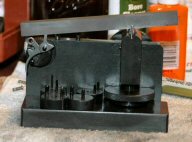
Next I installed the trigger in my Power Custom Series 1
stoning fixture using the BH (Blackhawk) adapter.
I used a blue marker to mark the surface and adjusted
the fixture until I was polishing the surface perfectly flat
and square. I used
my coarse ceramic stick to polish off all of the grinding/
machine tool marks, then final polished with my fine ceramic
stick.
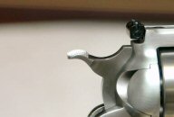
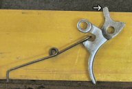 Finally
I cut the break-away angle in the trigger sear.
The arrow in the left photo shows which corner I cut.
Cutting this angle causes less surface area of the sear
to ride on the hammer notch. With
the trigger still installed on the BH adapter, I rotated the
adapter until I could cut the corner at a 45o
angle. I used a
220 grit narrow stone to cut the corner.
I used about 30 strokes, then cleaned and oiled the
surface. I had to
be very careful here. If
I cut the angle too deep the sear would slip off of the
trigger. The goal
was to make the trigger pull crisp, but still be safe. Finally
I cut the break-away angle in the trigger sear.
The arrow in the left photo shows which corner I cut.
Cutting this angle causes less surface area of the sear
to ride on the hammer notch. With
the trigger still installed on the BH adapter, I rotated the
adapter until I could cut the corner at a 45o
angle. I used a
220 grit narrow stone to cut the corner.
I used about 30 strokes, then cleaned and oiled the
surface. I had to
be very careful here. If
I cut the angle too deep the sear would slip off of the
trigger. The goal
was to make the trigger pull crisp, but still be safe.
 I
re-assembled the gun and tested the trigger.
With the 17 lb. hammer spring installed, it broke at
exactly 2.5 pounds every time with no creep.
To test for safety, with the hammer cocked I pushed on
the rear of the hammer with my thumb as hard as I could.
If the hammer didn’t slip off of the sear then I knew
it was safe. I
re-assembled the gun and tested the trigger.
With the 17 lb. hammer spring installed, it broke at
exactly 2.5 pounds every time with no creep.
To test for safety, with the hammer cocked I pushed on
the rear of the hammer with my thumb as hard as I could.
If the hammer didn’t slip off of the sear then I knew
it was safe.
I decided
to re-install the factory 23 lb. mainspring to get a little
quicker lock time. This
brought the trigger pull up to a very crisp 2.75 lbs.
This should help me stay on target during that all
important shot with the target in my sights.
Checkering
the Hammer Spur
The wide spur hammer I purchased came with horizontal grooves
cut in the spur. I
wanted to increase the grip by cutting vertical grooves
thereby checkering the spur.
First I
took a flat jeweler’s file and using the top groove as a
guide, cut a deep notch in front of the spur.
This provided clearance for my checkering file.
I took my 20 lines-per-inch (LPI) checkering file and
cut the vertical lines. I
believe the hammer was surface hardened because making the
initial cuts was somewhat difficult.
Once I broke through the surface, however, the cutting
proceeded smoothly. First
I cut all the vertical lines as deeply as I could with the
checkering file. Then
I went back and cleaned up each individual line with a
3-square file.
 After
cleaning up all the individual lines I took a half-round
jeweler’s file and cleaned up the excess cuts on the top of
the hammer, then shoe-shined this area with strips of 320 grit
wet/dry paper. After
re-assembling the gun I definitely got better gripping
purchase on the spur. The
checkering digs more sharply into my thumb for more positive
cocking. This will
be important in the field, especially in wet conditions or if
I’m wearing gloves because of the cold. After
cleaning up all the individual lines I took a half-round
jeweler’s file and cleaned up the excess cuts on the top of
the hammer, then shoe-shined this area with strips of 320 grit
wet/dry paper. After
re-assembling the gun I definitely got better gripping
purchase on the spur. The
checkering digs more sharply into my thumb for more positive
cocking. This will
be important in the field, especially in wet conditions or if
I’m wearing gloves because of the cold.
Hand-checkering
is a very time-consuming process.
Just to cut the vertical lines on probably 6/10 square
inch of hammer spur took me over 2 hours.
But the result was well worth the effort.
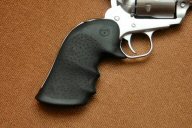
Installing
Hogue Mono-Grip
I purchased a Hogue slip-on one piece rubber grip for the
Blackhawk. I love
these grips and have them installed on all my double-action
revolvers. They do
an excellent job of helping to control recoil and they should
do the same on the Hog Hammer.
 The grip is
designed to fit both the Blackhawk and Super Single Six and
comes with two cross pins for different sizes of grip frames.
I couldn’t get the nut to fit on my grip frame so I
took a narrow Swiss pillar file and filed the bottom notch
deeper in the grip frame.
Once I got the nut in place and installed the narrow
cross pin, I slid the grip into place.
It didn’t fit perfectly so I took a knife and removed
a bit of rubber from the inside bottom of the grip.
Now it fit perfectly and screwed down tightly in place. The grip is
designed to fit both the Blackhawk and Super Single Six and
comes with two cross pins for different sizes of grip frames.
I couldn’t get the nut to fit on my grip frame so I
took a narrow Swiss pillar file and filed the bottom notch
deeper in the grip frame.
Once I got the nut in place and installed the narrow
cross pin, I slid the grip into place.
It didn’t fit perfectly so I took a knife and removed
a bit of rubber from the inside bottom of the grip.
Now it fit perfectly and screwed down tightly in place.
Wow, this
is a large grip! It’s
almost too big for my hand and may take some getting used to.
However, the size should help in controlling recoil,
which was the original plan.
I’ll have to do some test firing to see how it feels
in my hand, especially with gloves on.
In theory, by the time I port the barrel and add the
weight of a scope mount and optics, recoil should be pretty
tame.
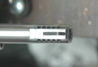
Porting
the Barrel
Ok, now for some serious metal work.
I planned to mill five 1/8” holes along each edge of
the front sight base in a ‘V’ pattern, hence the name
V-10. The outside
diameter of the barrel is 0.7” and the width of the front
sight base is 0.37”. That
puts each edge about 30° off vertical center.
Rather than drill each hole pointing towards the center
of the bore, I planed to drill them aligned as closely to
vertical as possible, which should help control recoil more
effectively.
Based on
other articles I’ve read on the Internet, starting 0.325”
from the end of the barrel, each 1/8” hole will be 0.1875”
apart. I set the
barrel on a 1” parallel in my machinist vise and rotated it
until the front sight base was resting against the edge of the
vise. Then I
positioned the bit 0.010” away from the sight base itself.
With my dial indicator properly set up to measure
distance between holes I was ready to begin milling.
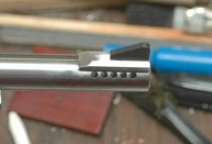
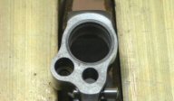
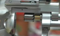
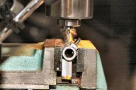 The article
suggested using a round end carbide bit to avoid leaving a
burr on the inside of the barrel; bad idea!
Not only did I break two bits, but I left a burr inside
the barrel on each hole. In
the left photo you can see the end of a broken bit at 3
o’clock inside the barrel.
What I should have done was use a flat end mill bit,
and driven a copper- jacketed bullet into the bore to drill
into to prevent burrs. I
used plenty of cutting oil to keep the bit and barrel cool,
and plunged the bit very slowly.
Still I was plunging too quickly when the bit broke
through on two holes and as a result I broke two bits. The article
suggested using a round end carbide bit to avoid leaving a
burr on the inside of the barrel; bad idea!
Not only did I break two bits, but I left a burr inside
the barrel on each hole. In
the left photo you can see the end of a broken bit at 3
o’clock inside the barrel.
What I should have done was use a flat end mill bit,
and driven a copper- jacketed bullet into the bore to drill
into to prevent burrs. I
used plenty of cutting oil to keep the bit and barrel cool,
and plunged the bit very slowly.
Still I was plunging too quickly when the bit broke
through on two holes and as a result I broke two bits.
Ok, after
cleaning up all the holes I had a number of burrs to remove.
First I chucked the frame and barrel in my vise muzzle
up resting on a piece of leather, and started driving bullets
down the bore. I
started with pure lead round ball, then went to hard cast
lead, then finally drove copper jacketed bullets down the
bore. During this
process I discovered another problem with this gun; there was
a constriction in the barrel where the threads were screwed
into the frame. Apparently
this is quite common for revolver barrels, especially Rugers
of .44 and .45 calibers, and can’t be good for accuracy.
There are
some methods to correct this; either fire-lap, hand-lap, or
swag the barrel. I
decided to try swaging by first impregnating copper-jacketed
bullets with 400 girt lapping compound, then driving them
through the bore. After
about 50 bullets or so all of the burrs were removed from the
right port holes, but the left holes still showed some
scraping of the bullets indicating a burr.
This was the side where I broke the two bits, which
left larger burrs.
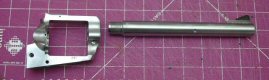
Hand-Lapping
the Barrel
Hand-lapping involved making a pure lead lap, impregnating it
with lapping compound, and running it down the bore by hand.
First, however, I needed to remove the barrel from the
frame.
I always
feel as if I’m encroaching into a forbidden area when I
separate a barrel from a frame; almost as if I’m not
allowed! There’s
only one right way to remove the barrel from the frame and
that’s with a barrel vise and action wrench; both of which
are available from Brownells.
Before I completely disassembled the gun I used a prick
punch to mark the position of the barrel in relation to the
frame. I placed
the witness marks on the bottom of the barrel between the
ejector shroud and cylinder pin holes so they wouldn’t show
when the gun was reassembled.
These marks ensured I had the barrel properly indexed
to the frame for reassembly.
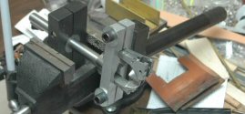
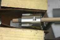
I attached
the action wrench to the frame using the Blackhawk receiver
blocks, and attached the barrel vise to the barrel using an
aluminum bushing I had to make with my hobby CNC mill.
I clamped the barrel vise vertically in my bench vise
and the barrel came off with very little effort.
Like my father used to say, “The job is always easier
when you have the right tools!”
(Ok, I can calm down now; no damage and I didn’t mar
the barrel!)
 Now that I
had the barrel separated from the receiver I was ready to
begin hand-lapping. First
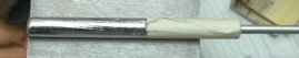
I had to make the lap. I
filled my electric lead pot with pure lead and prepared my
dipper. I took a
.243 caliber brass cleaning brush and screwed it onto the end
section of a multi-section rifle cleaning rod (no handle so I
could push it out of the barrel after pouring the lead).
Then I wrapped the end of the rod where the brush
screwed in with masking tape so it would fit tightly into the
barrel. I inserted
this into the barrel from the muzzle end until the end of the
brush was about 1/4“ below the forcing cone.
(I couldn’t pour from the muzzle end because lead
would fill the ports and I’d never be able to remove the
lap!) Then I
wrapped the barrel threads with masking tape, which protected
them from both lead and lapping compound.
I wrapped a piece of suede around the barrel and held
it at an angle with a pair of pliers, then used my lead dipper
to pour lead down the barrel over the cleaning brush.
I stopped pouring just before the lead got to the
forcing cone. I
put the barrel in my vise and tapped out the lap. Now that I
had the barrel separated from the receiver I was ready to
begin hand-lapping. First
I had to make the lap. I
filled my electric lead pot with pure lead and prepared my
dipper. I took a
.243 caliber brass cleaning brush and screwed it onto the end
section of a multi-section rifle cleaning rod (no handle so I
could push it out of the barrel after pouring the lead).
Then I wrapped the end of the rod where the brush
screwed in with masking tape so it would fit tightly into the
barrel. I inserted
this into the barrel from the muzzle end until the end of the
brush was about 1/4“ below the forcing cone.
(I couldn’t pour from the muzzle end because lead
would fill the ports and I’d never be able to remove the
lap!) Then I
wrapped the barrel threads with masking tape, which protected
them from both lead and lapping compound.
I wrapped a piece of suede around the barrel and held
it at an angle with a pair of pliers, then used my lead dipper
to pour lead down the barrel over the cleaning brush.
I stopped pouring just before the lead got to the
forcing cone. I
put the barrel in my vise and tapped out the lap.
 I started
with 220 grit lapping compound and found this was so coarse
that I had to drive the lap through the barrel with a mallet.
Because of this I drove the lap always from the forcing
cone to the muzzle (same direction as bullet travel) and tried
to line up the rifling the same way every time.
Once I mis-aligned the rifling so I had to remake my
lap. I thoroughly
cleaned and oiled the barrel before doing another pour.
After every 20 passes I cleaned and slugged the barrel.
It took about 40 passes to remove the constriction in
the barrel. I started
with 220 grit lapping compound and found this was so coarse
that I had to drive the lap through the barrel with a mallet.
Because of this I drove the lap always from the forcing
cone to the muzzle (same direction as bullet travel) and tried
to line up the rifling the same way every time.
Once I mis-aligned the rifling so I had to remake my
lap. I thoroughly
cleaned and oiled the barrel before doing another pour.
After every 20 passes I cleaned and slugged the barrel.
It took about 40 passes to remove the constriction in
the barrel.
I cleaned
the barrel and made a new lap and impregnated it with 400 grit
compound. This was
fine enough that I could move the lap back and forth by hand.
I made sure I pushed and pulled the lap so most of it
was exposed before reversing direction.
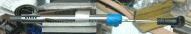
Note in Figure 16 above that the barrel is mounted in
the vise using the aluminum barrel bushing I used to remove
the barrel. Some
experts say that if you squeeze the barrel linearly in a vise
you can cause the barrel to be somewhat egg shaped after
lapping. I tried
final polishing with 800 grit but it was too fine and the lap
was too small to really do much good. After
completing the hand lapping process I again slugged the
barrel. This time the barrel was smooth with no
constriction and all burrs were removed.
Lapping
Barrel Shoulder to Frame
Before reassembling the gun I wanted to lap the barrel
shoulder to the frame. Most
production rifles and revolvers where the barrel is screwed
into the frame are usually way too tight.
This can cause two problems; a constriction in the
barrel at the threads (which I had!), and if the barrel
shoulder and frame are not perfectly square undue stress is
applied to both the barrel and frame which ultimately affects
accuracy. (Since
every firearm is different this may not apply to every one.)
The solution to both problems is to lap the barrel
shoulder to the frame.

In the left
photo above, I have begun the lapping process.
I was careful not to get any lapping compound on the
threads. This
would cause a loose fit. With
the barrel shoulder just touching the frame, the distance
between the witness marks was about 1/4“.
This indicated just how tightly the barrel was screwed
into the frame.
With 400
grit lapping compound applied only to the frame I continually
tightened and loosened the barrel by hand.
I occasionally recharged the compound again being
careful not to get any on the barrel threads.
I stopped when the two witness marks were a little over
1/8” apart and cleaned off the lapping compound.
The grey area in the above center photo indicates that I’ve lapped
the shoulder completely around the frame.
The above right photo shows the location of the witness marks
after lapping.
Re-Attaching
the Barrel
Now that the shoulder is lapped to the frame I’m ready to
reassemble the gun. Since
the barrel won’t be as tight as before I used Loctite to
make sure the barrel stayed in place.
I cleaned the threads on both the barrel and frame,
barrel shoulder and front of the frame with acetone and a
cotton swab. I
applied Loctite 222 to the threads, and Loctite 609 to the
shoulder. Loctite
222 (purple) is a low strength thread locker, and Loctite 609
(green) is specifically made for use where metal contacts
metal such as for pressed fittings.
This is just right for use where the barrel shoulder
contacts the frame. I
let this set for 24 hours before doing any additional work.
After
waiting 24 hours I slugged the barrel again and was pleased to
find the barrel constriction was gone, the burrs were gone,
and the barrel was nice and smooth.
The slug measured exactly 0.451”, which told me I
needed to size my cast loads to 0.452” for maximum accuracy.
I reassembled the gun using blue Loctite on all screws.
Barrel/Cylinder
Gap
One of the other
advantages to lapping the shoulder of the barrel was to reduce
the barrel/cylinder gap. Since
I removed metal from both the barrel shoulder and frame, the
end of the barrel was now closer to the end of the cylinder.
After reassembling the gun my barrel/cylinder gap was
less than 0.0015” which is way too small to be safe.
I used a 0.625” facing cutter with .45 pilot bushing
and guide to cut the face of the barrel forcing cone to
0.003”. Three
thousandths should be more than enough for safety, but provide
a nice tight gun.
I just
lightly started to cut and it opened the gap to 0.003”.
I discovered the end of the barrel was not square
because I only cut half of the surface, the other half was not
touched. I would
have preferred 0.002” but this will be ok.
Reaming
Cylinder Throats
Undersized cylinder throats are another common problem with Ruger single action
revolvers. The key
here was to ensure the cylinder throats were close to the same
diameter as the bullets.
Since my barrel slugs to 0.451” I need to size my
bullets to 0.452”, which meant my cylinder throats should
also be 0.452” – 0.4525”.
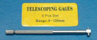
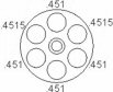
I measured
the cylinder throats using my smallest telescoping gauge and
they were 0.451” – 0.4515”.
I had used 0.452” bullets to fire-lap, and from the
cylinder throat measurements it looked like I did a good job
of lapping just the cylinder throats; they were consistent,
but undersized for 0.452” bullets.
As a comparison I measured the throats of two Ruger
Vaqueros I have and my friend’s Bisley Blackhawk, all in .45
LC. They measured
from 0.450” - 0.451”, all somewhat undersized.
 I cut a
slit in a piece of 3/8” dowel and wrapped a strip of 320
grit wet/dry paper around it so it would fit snuggly in the
chamber throat. I
attached the other end of the dowel to my drill, inserted the
reamer through the chamber and ran the drill at a medium speed
while moving the reamer in and out.
I reamed each throat until it measured 0.4525”.
This not only opened up the throats, but polished them
mirror-smooth, which made them much easier to clean.
For each chamber throat I first reamed as described
above, reversed the paper to use the other end and reamed
again. This was
all it took to open up each throat. I cut a
slit in a piece of 3/8” dowel and wrapped a strip of 320
grit wet/dry paper around it so it would fit snuggly in the
chamber throat. I
attached the other end of the dowel to my drill, inserted the
reamer through the chamber and ran the drill at a medium speed
while moving the reamer in and out.
I reamed each throat until it measured 0.4525”.
This not only opened up the throats, but polished them
mirror-smooth, which made them much easier to clean.
For each chamber throat I first reamed as described
above, reversed the paper to use the other end and reamed
again. This was
all it took to open up each throat.
Revolver
Accuracy
This information is from my article Accurizing
the Ruger Single-Action Revolver but it bears
repeating here. I’m going to pause a bit and
ruminate on what I’ve learned about revolver accuracy.
With my Blackhawk in its original factory condition
this is what would be happening:
- Burning
gunpowder forces 0.452”bullet out of case into cylinder
throat.
- Cylinder
throat swags bullet to 0.450”.
- Bullet
jumps cylinder gap into barrel forcing cone.
Actually, you have to stop to think about this for
a minute. In
reality, the base of the bullet is still in the case while
the nose is engaging the rifling.
- Barrel
constriction swags bullet another 0.002” so it is now
0.448”. (The
barrel constriction in some Rugers can be as much as
0.004”!)
- 0.448”
bullet is 0.003” undersize for the 0.451” bore, bullet
wobbles as it travels down the bore, gas leaks around the
bullet causing leading, who knows how it will exit the
muzzle, resulting in a very disappointing group.
This is
what should happen with a properly sized, fitted and lapped
revolver:
- Burning
gunpowder forces 0.452”bullet out of case into cylinder
throat.
- 0.4525”
cylinder throat guides bullet into the forcing cone, no
swaging occurs.
- Bullet
jumps cylinder gap into barrel forcing cone.
- No
barrel constriction exists so 0.452” bullet enters
0.451” barrel. Because
the bullet is 0.001” oversize all lands and grooves are
sealed.
- 0.451”
bullet is in constant contact with the bore because
fire-lapping slightly tapered the bore.
Bore is sealed, no gas cutting/leading occurs.
- Bullet
exit from muzzle is consistent resulting in excellent
groups.
Mounting
Scope and Red Dot Sight
I purchased a silver Weaver mount made especially for the
Ruger Blackhawk, but the slots were spaced too far apart to
mount the red dot sight. This
looked like another job for the milling machine.
I wanted the sight to be as far back as possible so I
used the rear slot as a guide and marked where I planned to
mill a new front slot. The
original slots were 0.152” wide, so I first made a cut with
a 1/8” (0.125”) end mill, then moved it 0.027” to finish
the slot.
I chucked
the base in my machinist vise, adjusted the horizontal,
vertical, and depth of the end mill bit and made my first cut
at the mark. Using
my dial indicator I moved the bit forward 0.027” and made
the second cut without changing the depth.
Now I can successfully mount the red dot sight.
After
mounting the red-dot sight I then mounted the 2x pistol scope.
This was a simple matter of mounting the ring bottoms
to the scope mount, then mounting the scope and installing the
top rings. I put a
thin layer of clear silicon RTV inside both ring halves and
used blue Locktite on the ring screw threads.
Now this installation will not move under recoil.
Converting
Existing Pawl to a Free-Spin Pawl
The pawl is the arm that extends from inside the frame of the
revolver to engage the ratchet teeth on the rear of the
cylinder as you cock the hammer to index the cylinder to the
next chamber. With
the loading gate open the top of the pawl is in constant
contact with those teeth allowing the cylinder to rotate in
only one direction. A
free-spin pawl does not engage the cylinder with the loading
gate open thereby allowing the cylinder to rotate freely in
any direction during loading.
When the loading gate is closed the free-spin pawl
works as normal to engage the cylinder when the hammer is
pulled back. Over
the years I’ve tried using the after-market free-spin pawls
but they seem to alter the trigger pull.
This was caused by the press-fit pin backing out
causing the pawl to drag against the frame. Refer to my
article Making
a Free Spin Pawl for a Ruger Single-Action Revolver
for details on this process.
 Ballistics
and Sighting In Ballistics
and Sighting In
I am using Lee bullet mold C452-300-RF which is a 300
grain .452 wide flat point bullet that takes a gas check.
I hard cast this bullet using a linotype mixture.
At the time I size and lubricate it I install the gas
check. Although
this is a very hard lead alloy, I still use the gas check
because of the velocity at which I am pushing this bullet.
This bullet comes with two crimping grooves.
The chambers in the Ruger are long enough that I can
crimp on the bottom groove, thereby reducing the amount of
distance the bullet has to jump from cylinder to barrel.
(These long rounds would not fit in my friend’s
Bisley Blackhawk because his 0.451” chamber throats were too
narrow.) By the
way, I’ve used these rounds as a gauge to determine if the
chamber throats have been reamed enough.
I measured
the ballistic coefficient (BC) for this bullet at .24 for my
particular atmospheric conditions.
(I did this by measuring the muzzle velocity and the
downrange velocity.) Lee
publishes the ballistic coefficient at .233 which is very
close to my calculations.
Using my ballistic program and knowing the velocity and
BC, I calculated point blank range.
Point blank range is defined as the maximum distance
the bullet can travel and stay within a specific diameter
circle. I wanted
to stay within a 4” circle (+2.0” above the line of sight,
and -2.0” below the line of sight.)
Based on this data the point blank range is
110 yards, sighted in at 95 yards.
(I’ll probably limit my shooting to 60 yards or
less.)
To get the
rounds sighted in I went to my local indoor range, which is
limited to 25 yards. Using
the same calculations above to be sighted in for 95 yards the
bullet should strike 0.75” high at 25 yards.
So this is where I will adjust both the scope and red
dot sight.
With this
accurized gun I regularly shoot 1/2" groups at 25 yards.
This made all my work worthwhile, and it certainly paid
off in improved accuracy.
Lessons
Learned
This project has taught me quite a bit about revolver
accuracy. I also
discovered there are proper steps to accurizing the revolver
depending on my goals. If
I didn’t want to adjust the barrel to cylinder gap I would
have slugged the barrel to determine the correct cast bullet
size, opened up the cylinder throats to accommodate that
bullet size, and removed the constriction by fire-lapping.
Since I wanted to squeeze out as much accuracy as I
could and I wanted to adjust the barrel to cylinder gap, I
removed the barrel, hand-lapped it, lapped the shoulder and
frame, reassembled, then adjusted the gap.
Then I adjusted the cylinder throats based on slugging
the barrel.
As
mentioned before, my friend’s Bisley Blackhawk has cylinder
throats that measure 0.451”, his barrel has a 0.001”
constriction, his barrel/cylinder gap is 0.007”, and the
trigger pull is 2 pounds, but long and creepy.
At a minimum I would do an action job, open the chamber
throats to 0.4525”, and fire-lap the barrel.
If he wanted the barrel/cylinder gap closed up, I would
remove the barrel, hand-lap it, then lap the barrel shoulder
to the frame.
Tool
and Parts List
Following are the tools and parts I used for this project.
|